
3 Wire Voltage Regulator Wiring Diagram
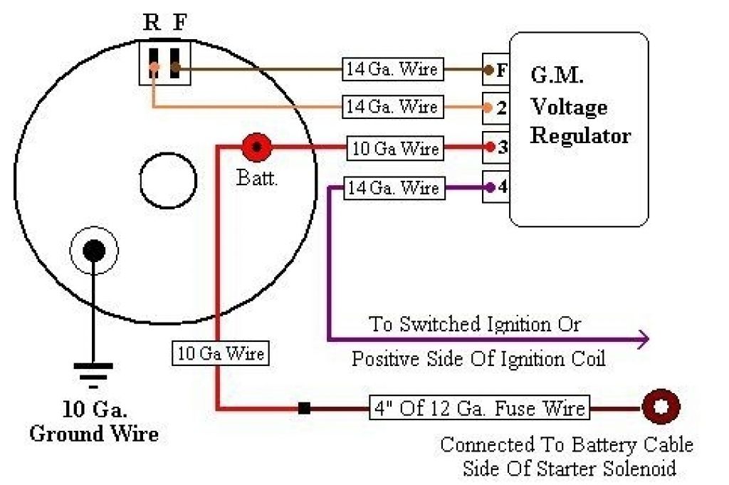
Let's talk about 3-wire voltage regulators. If you're tinkering with car electrical systems, especially older vehicles or custom builds, understanding how these little devices work and how to wire them is absolutely crucial. This article will walk you through a typical 3-wire voltage regulator wiring diagram, explaining the purpose, components, functionality, and even some basic troubleshooting. We'll present this information as if I'm your trusted mechanic, explaining things clearly and directly for an experienced DIYer like yourself. We even have a downloadable diagram available for you at the end of this article.
Why Understanding 3-Wire Voltage Regulators Matters
Why bother diving into this? Well, a properly functioning voltage regulator is vital for a healthy electrical system. Its main job is to maintain a stable voltage output to the car's electrical components, preventing overcharging the battery and protecting sensitive electronics from voltage spikes. Knowing the wiring diagram allows you to:
- Diagnose and Repair Issues: Identify a faulty regulator, wiring problems, or blown fuses.
- Perform Upgrades or Modifications: Integrate aftermarket alternators or batteries safely.
- Understand Electrical System Fundamentals: Gain a deeper understanding of automotive charging systems, and electricity in general.
- Prevent Costly Damage: Stop electrical components, including your battery, from being destroyed.
Key Specs and Main Parts
Before we get to the wiring, let's quickly cover the main components and some key specs. A typical 3-wire voltage regulator setup interacts with the following:
- Alternator: The heart of the charging system, generating AC voltage that's then rectified to DC. You'll generally find the alternator voltage around 13.5V - 14.5V when properly working.
- Voltage Regulator: The brain of the system, controlling the alternator's output voltage. It achieves this by regulating the field current to the alternator.
- Battery: The energy storage device, supplying power when the engine isn't running and assisting during high-demand situations. Typically 12V, but keep an eye on the specific battery voltage of your vehicle.
- Wiring Harness: Connects all the components together. Crucial for providing the correct voltage, signals, and ground paths.
Important Specs to Consider:
- Voltage Setpoint: The target voltage the regulator aims to maintain (usually around 14.2V).
- Current Capacity: The maximum current the regulator can handle.
The 3 Wires:
In the 3-wire configuration, you'll typically find these:
- Battery Sense (Voltage Sense): Monitors the battery voltage. This is a critical input for the regulator, as it determines how much field current the regulator will send to the alternator.
- Ignition (Exciter/Switch): Provides a switched 12V+ source to activate the regulator when the ignition is turned on. This is the trigger that enables the regulator to start doing its job.
- Field (Alternator Field): Connects to the alternator's field winding, allowing the regulator to control the alternator's output by varying the current flowing through the field winding.
Wiring Diagram Symbols and Conventions
Understanding the symbols used in a wiring diagram is essential for proper interpretation. Common symbols include:
- Solid Lines: Represent wires. Thicker lines generally indicate wires carrying higher current.
- Dotted Lines: May represent a shielded cable or a wire that is part of a wiring harness.
- Ground Symbol: Usually represented by a series of descending lines or a triangle. Indicates a connection to the vehicle's chassis (ground).
- Battery Symbol: Two or more alternating long and short parallel lines. Shows the positive and negative terminals of the battery.
- Resistor Symbol: Zigzag line.
- Switch Symbol: A line that can be connected or disconnected to another line, indicating an open or closed circuit.
- Alternator Symbol: A circle with a three-phase sine wave inside.
Color Coding: While not universal, common color codes include:
- Red: Typically used for positive battery connections.
- Black: Typically used for ground connections.
- Other Colors (Blue, Green, Yellow, White): Used for signal or control wires, like the ignition wire. Consult the specific diagram for your vehicle.
How a 3-Wire Voltage Regulator Works
Okay, let's break down how this whole system actually functions:
- Ignition On: When you turn the ignition key, the Ignition wire receives 12V+, activating the voltage regulator.
- Voltage Sensing: The regulator constantly monitors the battery voltage via the Battery Sense wire.
- Field Current Control: Based on the battery voltage, the regulator adjusts the current flowing through the Field wire to the alternator's field winding.
- Alternator Output Adjustment: The amount of current flowing through the field winding directly affects the alternator's output voltage. Higher field current equals higher output voltage.
- Feedback Loop: The system operates in a closed-loop feedback. If the battery voltage is low, the regulator increases the field current, boosting the alternator's output. If the battery voltage is high, the regulator decreases the field current, reducing the alternator's output. The regulator is constantly aiming to maintain the voltage setpoint.
Essentially, the voltage regulator acts like a smart thermostat, constantly adjusting the "heat" (alternator output) to maintain a stable "temperature" (battery voltage).
Real-World Use: Basic Troubleshooting
So, what happens when things go wrong? Here are a few basic troubleshooting tips:
- Overcharging (Battery Boiling): Check the voltage sense wire. If it's disconnected or has a poor connection, the regulator won't "see" the battery voltage and will keep pumping out maximum voltage. Also, check the regulator itself; it may be faulty.
- Undercharging (Battery Constantly Drained): Check the ignition wire. If it's not receiving power, the regulator won't activate. Also, check the alternator's brushes and the field winding for continuity. The alternator may be dead.
- No Charging at All: Check all wiring connections. A loose connection or corroded terminal can prevent the system from working. Check fuses. A blown fuse on the ignition wire can disable the regulator.
Using a Multimeter: A multimeter is your best friend for troubleshooting. You can use it to:
- Measure voltage at the battery, alternator, and regulator terminals.
- Check for continuity in wires and fuses.
- Measure resistance of the field winding.
Safety Considerations
Working with automotive electrical systems can be dangerous. Here are some safety precautions:
- Disconnect the Battery: Always disconnect the negative battery cable before working on the electrical system. This prevents accidental shorts and shocks.
- Work in a Well-Ventilated Area: Batteries can produce explosive gases.
- Wear Eye Protection: Protect your eyes from battery acid and flying debris.
- Be Careful Around Moving Parts: Keep your hands and tools away from the engine while it's running.
- Capacitors within the Alternator: Be aware that alternators can store a charge even after the battery is disconnected. Discharging the alternator before working on it is a good practice.
High-Risk Components: The alternator and battery can deliver significant current. Treat them with respect!
Understanding the 3-wire voltage regulator wiring diagram is a key skill for any serious automotive DIYer. Armed with this knowledge, you'll be able to diagnose, repair, and modify your vehicle's charging system with confidence. Remember to always consult the specific wiring diagram for your vehicle, as wiring configurations can vary.
As promised, we have a downloadable version of a typical 3-wire voltage regulator wiring diagram. You can find it here: [Insert Link to Diagram File Here].