3.5 Firing Order 2006 Nissan Murano Ignition Coil Diagram
Alright, let's dive into the ignition system of your 2006 Nissan Murano, specifically focusing on the firing order and the ignition coil diagram. This is crucial information for anyone looking to perform diagnostics, maintenance, or even some performance upgrades on their vehicle. Having a solid understanding of these aspects will save you time, money, and a whole lot of frustration.
Purpose of the Ignition Coil Diagram
Why bother with a diagram in the first place? Well, the ignition coil diagram is your roadmap to the engine's firing sequence and the electrical components that make it all happen. It's essential for several reasons:
- Troubleshooting misfires: Knowing which coil corresponds to which cylinder allows you to pinpoint the source of a misfire quickly.
- Replacing ignition coils: Ensures you're installing the new coil in the correct location.
- Diagnosing wiring issues: The diagram shows the wiring connections between the ECU (Engine Control Unit), the coils, and other sensors, helping you trace faults in the electrical system.
- Performance modifications: Understanding the ignition system is fundamental if you're planning to install aftermarket coils, spark plugs, or even a standalone ECU.
- General learning: Even if you aren't wrenching on your Murano today, understanding how the ignition system works is valuable knowledge for any car enthusiast.
Key Specs and Main Parts of the 2006 Nissan Murano Ignition System
The 2006 Nissan Murano uses a 3.5-liter V6 engine (VQ35DE). This engine uses a distributorless ignition system, meaning each cylinder has its own dedicated ignition coil. This is a coil-on-plug (COP) design.
Key Specs:
- Engine Type: VQ35DE, 3.5L V6
- Firing Order: 1-2-3-4-5-6
- Ignition System Type: Coil-on-Plug (COP), Distributorless
- ECU: Controls the timing and duration of the spark.
- Crankshaft Position Sensor (CKP): Provides the ECU with information about the crankshaft's position and speed.
- Camshaft Position Sensor (CMP): Provides the ECU with information about the camshaft's position.
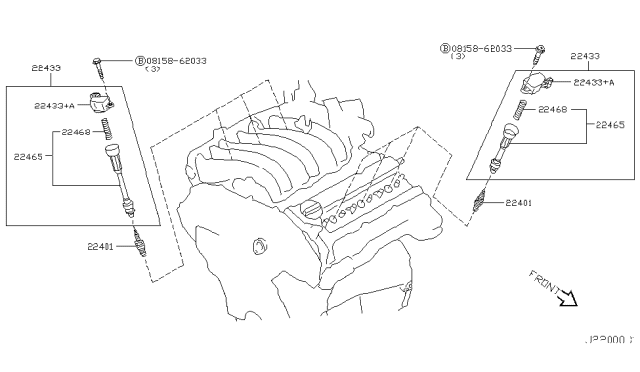
Main Parts:
- Ignition Coils: One coil per cylinder. These are responsible for stepping up the battery voltage (12V) to a high voltage (typically 20,000-30,000 volts) needed to create a spark across the spark plug gap.
- Spark Plugs: Located inside the combustion chamber, they ignite the air-fuel mixture.
- ECU (Engine Control Unit): The brain of the engine, controlling the ignition timing based on various sensor inputs.
- Wiring Harness: Connects all the components of the ignition system.
Decoding the Ignition Coil Diagram: Symbols and Conventions
The ignition coil diagram is a schematic representation of the electrical circuit. Here's a breakdown of common symbols you might encounter:
- Solid Lines: Represent wires or conductors. The thickness of the line *usually* doesn't indicate anything about the wire's gauge, although some advanced diagrams might use varying thickness.
- Dotted Lines: Often indicate shielded wires or communication links, such as CAN bus lines.
- Coil Symbol (typically a series of curved lines): Represents the ignition coil itself.
- Ground Symbol (often three descending lines): Indicates a connection to the vehicle's chassis ground.
- Connector Symbols (circles, squares, or a combination): Show where wires connect and disconnect. They'll often be labeled with a number or letter to identify the specific connector.
- Component Boxes: Represent various components like the ECU, sensors, and relays.
- Wire Colors: Usually indicated by abbreviations (e.g., "BLU" for blue, "RED" for red, "BLK" for black). Pay close attention to these, as matching wire colors is crucial when troubleshooting.
The diagram will also show the pin numbers of the ECU connector that control each ignition coil. These are essential for testing the ECU's output signal.
How the Ignition System Works
The ignition system's job is to ignite the air-fuel mixture inside the cylinders at precisely the right time. Here's how it works on your 2006 Murano:
- Sensor Input: The Crankshaft Position Sensor (CKP) and Camshaft Position Sensor (CMP) provide the ECU with information about the engine's speed and position.
- ECU Calculation: Based on the sensor data and other factors (like throttle position and engine temperature), the ECU determines the optimal ignition timing.
- Coil Activation: The ECU sends a signal to each ignition coil to energize its primary winding. This rapidly builds up a magnetic field inside the coil.
- Spark Generation: When the ECU de-energizes the primary winding, the magnetic field collapses. This induces a high-voltage current in the secondary winding of the coil.
- Spark Plug Ignition: The high-voltage current is sent to the spark plug, creating a spark across the electrode gap. This spark ignites the compressed air-fuel mixture in the cylinder.
The firing order (1-2-3-4-5-6) dictates the sequence in which the cylinders fire. The ECU ensures that each coil fires at the correct moment in the engine's cycle. This precise timing is crucial for optimal engine performance, fuel efficiency, and emissions control.
Real-World Use: Basic Troubleshooting Tips
Let's put this knowledge into practice with some basic troubleshooting:
- Misfire Diagnosis: If you're experiencing a misfire, use an OBD-II scanner to identify the cylinder causing the problem. Once you know the cylinder number, use the ignition coil diagram to identify the corresponding coil. You can then swap the coil with another cylinder to see if the misfire follows the coil. If it does, the coil is likely faulty.
- Testing Ignition Coils: You can test the primary and secondary resistance of the ignition coils using a multimeter. Compare your readings to the manufacturer's specifications. Out-of-spec readings indicate a faulty coil.
- Checking Wiring: Use the diagram to trace the wiring between the ECU and the coils. Look for damaged wires, loose connections, or corrosion. You can use a multimeter to check for continuity and voltage at the coil connectors.
- No Spark Condition: If you're not getting any spark at all, start by checking the CKP and CMP sensors. If these sensors are faulty, the ECU won't know when to fire the ignition coils. Also, check for power and ground at the ignition coils themselves.
Safety Considerations
Working with the ignition system involves high voltages and potentially flammable materials. Here are some important safety precautions:
- Disconnect the Battery: Always disconnect the negative battery cable before working on the ignition system. This will prevent accidental shocks or damage to the ECU.
- Handle Coils Carefully: Ignition coils can store a charge even after the engine is turned off. Avoid touching the terminals of the coil while it's disconnected.
- Work in a Well-Ventilated Area: When working with gasoline or other flammable materials, make sure you're in a well-ventilated area to prevent fire hazards.
- Use Proper Tools: Use insulated tools to avoid electrical shocks.
- Avoid Sparks Near Fuel: Be extremely careful when testing for spark. Avoid creating sparks near fuel lines or other flammable materials.
Ignition systems can produce extremely high voltages, which can be lethal. Always exercise caution and follow safety procedures. If you're not comfortable working on the ignition system, it's best to consult a qualified mechanic.
Remember, proper diagnostics are key. Don't just throw parts at the problem. Use the ignition coil diagram, a multimeter, and an OBD-II scanner to pinpoint the root cause of the issue. A systematic approach will save you time and money in the long run.
We have a copy of the full 2006 Nissan Murano ignition coil diagram available for download. It will be a valuable asset for your future repairs and upgrades.