350 Tbi 1994 Chevy 5.7 Firing Order Diagram
Alright, let's dive into the firing order diagram for the 1994 Chevy 5.7L (350 TBI) engine. This is a crucial piece of information, whether you're tackling a tune-up, diagnosing a misfire, or even just trying to understand how your engine operates. Knowing the firing order, and how to interpret the diagram, is absolutely essential for proper ignition timing and overall engine health.
Purpose of the Firing Order Diagram
Why bother with this diagram at all? Well, the firing order dictates the specific sequence in which the cylinders of your engine ignite the air-fuel mixture. If the spark plugs fire out of order, your engine will run rough, misfire, or simply not start at all. Understanding the firing order diagram allows you to:
- Correctly install spark plug wires: Ensuring each wire connects the distributor to the correct cylinder is paramount.
- Diagnose misfires: A consistent misfire on a specific cylinder often points to an issue with the corresponding spark plug, wire, or injector.
- Perform tune-ups: Knowing the firing order is essential for properly timing the ignition system.
- Understand engine operation: It provides a fundamental understanding of how a V8 engine functions.
Key Specs and Main Parts: 1994 Chevy 5.7L (350 TBI)
Before we dissect the diagram, let's establish some key specs for the 1994 Chevy 5.7L TBI (Throttle Body Injection) engine. Keep in mind that while most 350 small block Chevys share the same firing order, *always* confirm it for your specific year and model. This is especially important if the engine has been modified or swapped.
Key Specs:
- Engine Size: 5.7 Liters (350 Cubic Inches)
- Fuel Delivery: Throttle Body Injection (TBI)
- Configuration: V8
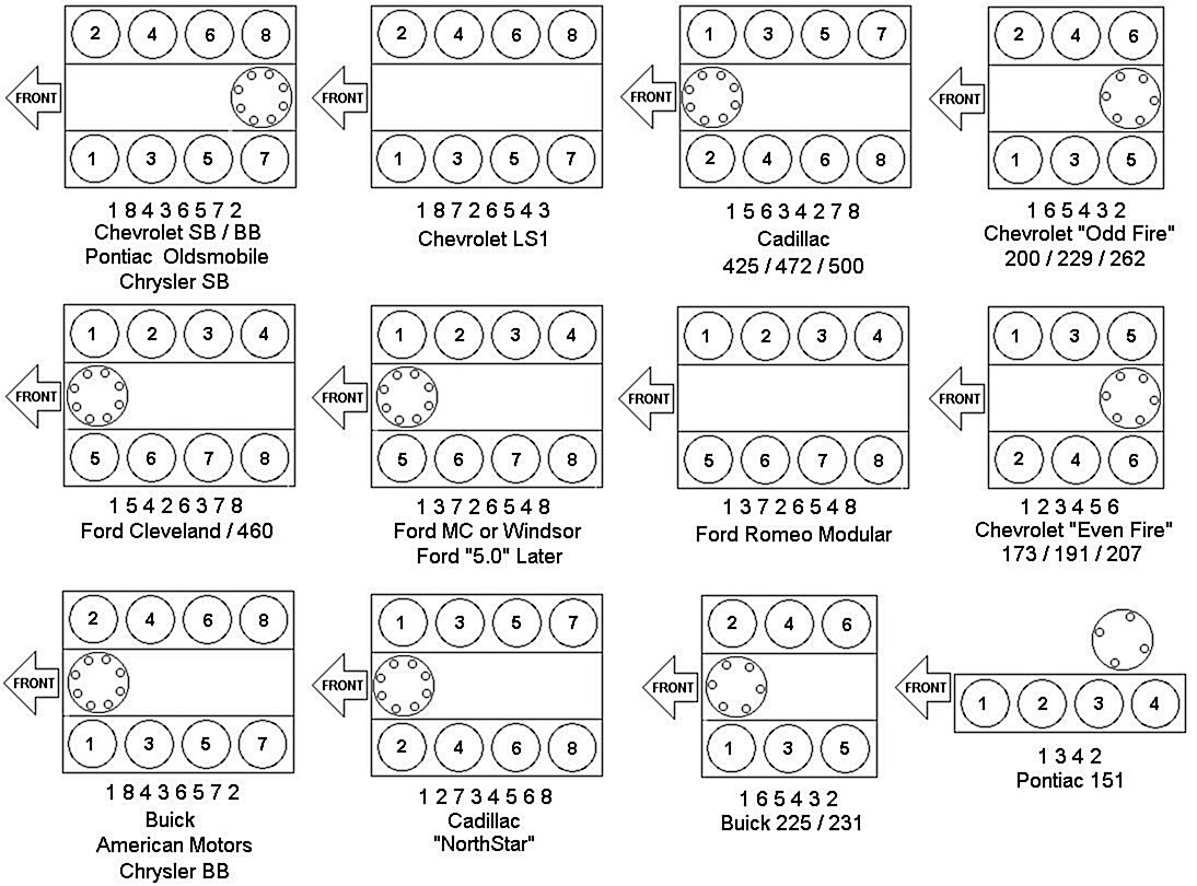
- Firing Order: 1-8-4-3-6-5-7-2
- Distributor Rotation: Clockwise
Main Parts Involved:
- Distributor: This component distributes high-voltage electricity to the spark plugs in the correct sequence.
- Distributor Cap: The cap sits on top of the distributor and has terminals that connect to the spark plug wires.
- Rotor: Located inside the distributor cap, the rotor spins and directs the high-voltage current to the correct terminal.
- Spark Plug Wires: These wires carry the high-voltage electricity from the distributor cap to the spark plugs.
- Spark Plugs: These ignite the air-fuel mixture in the cylinders.
- Cylinders: These are the combustion chambers within the engine block. Numbered 1-8.
Understanding the Diagram: Symbols and Conventions
A firing order diagram can seem daunting at first, but it's quite simple once you understand the conventions. Typical diagrams for the 350 TBI will usually feature:
- Engine Block Representation: An image, often simplified, of the V8 engine block, showing the cylinder arrangement. Typically, cylinder numbers are marked on each cylinder. It’s crucial to remember the numbering convention. On a Chevy small block, the driver's side cylinders are 1, 3, 5, and 7 (front to back), and the passenger's side are 2, 4, 6, and 8 (front to back).
- Distributor Representation: A top-down view of the distributor cap. This shows the terminals arranged around the center.
- Lines: Lines connect the terminals on the distributor cap to the corresponding cylinders on the engine block. These lines visually represent which spark plug wire goes where.
- Numbers: Numbers are associated with both the cylinders and the distributor terminals. These numbers directly correspond to the firing order (1-8-4-3-6-5-7-2). You’ll see the numbers around the distributor cap, indicating the order the spark is sent.
- Rotation Arrow: An arrow indicating the direction of distributor rotation (clockwise in this case). This is important for understanding the sequence of spark delivery.
The key to reading the diagram is to follow the lines from the distributor cap terminals to the correct cylinder. Start with the terminal marked "1" and trace the line to the corresponding cylinder. Then, find the terminal marked "8" and repeat, and so on. Following this sequence will ensure you install the spark plug wires in the correct firing order.
How It Works: The Ignition Process
Let's briefly explain how the ignition process ties into the firing order:
- The engine's crankshaft turns, driving the camshaft.
- The camshaft rotates the distributor shaft.
- As the distributor shaft spins, the rotor inside the distributor cap also rotates.
- The rotor passes by each terminal inside the distributor cap, allowing the ignition coil to send a high-voltage pulse to that terminal.
- The high-voltage pulse travels through the spark plug wire to the spark plug in the corresponding cylinder.
- The spark plug ignites the air-fuel mixture in the cylinder, causing combustion and pushing the piston down.
- This process repeats for each cylinder in the firing order, ensuring a smooth and efficient engine operation.
The firing order ensures that each cylinder fires at the precise moment required to maximize power and efficiency. An incorrect firing order disrupts this timing, leading to all sorts of problems.
Real-World Use: Basic Troubleshooting Tips
Here's how you can use the firing order diagram for basic troubleshooting:
- Misfire Diagnosis: If you're experiencing a misfire, use a scan tool to identify the affected cylinder. Then, check the spark plug, wire, and injector for that cylinder. Use the firing order diagram to confirm that the spark plug wire is connected correctly.
- Rough Idle: A rough idle can sometimes be caused by incorrect spark plug wire placement. Double-check the wiring against the firing order diagram.
- Engine Won't Start: If your engine won't start, ensure that all spark plug wires are properly connected and that the distributor cap is in good condition. The firing order is a good place to start.
- Recent Work: Did you just change the spark plugs, wires, or distributor cap? An incorrect wiring is a common problem, so re-verify with the diagram.
Troubleshooting Steps:
- Visually inspect all spark plug wires for damage (cracks, burns, etc.).
- Check the connections at both the distributor cap and the spark plugs.
- Use a multimeter to test the resistance of each spark plug wire. Excessive resistance can indicate a faulty wire.
- Inspect the distributor cap for cracks or carbon tracking (black lines indicating arcing).
- Consider a timing light to verify timing.
Safety Considerations
Working on the ignition system involves high voltage, so safety is paramount. Here are some key safety precautions:
- Disconnect the Battery: Always disconnect the negative battery cable before working on the ignition system to prevent accidental shocks.
- Avoid Touching Wires While Engine is Running: Never touch spark plug wires or the distributor cap while the engine is running, as this can result in a severe electric shock.
- Work in a Well-Ventilated Area: When working with fuel, work in a well-ventilated area to avoid inhaling harmful fumes.
- Fuel Lines: TBI systems have pressurized fuel lines. If you need to disconnect any fuel lines, relieve the pressure first. Usually, this is done via a Schrader valve on the fuel rail.
High voltage can be lethal. Always exercise caution and follow safety guidelines when working on the ignition system.
With the information above, you should now have a solid understanding of the 1994 Chevy 5.7L TBI firing order diagram and how to use it for maintenance and troubleshooting. Remember to always double-check your work and consult a qualified mechanic if you're unsure about any procedure. Correct cylinder identification and tracing wires is key for success.