3.9 Liter Dodge Dakota 3.9 V6 Engine Diagram
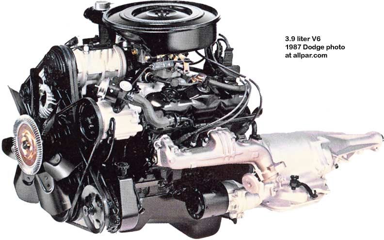
The 3.9-liter V6 engine, a staple in the Dodge Dakota from the late 80s through the early 2000s, is a robust but straightforward power plant. Understanding its intricacies through a detailed engine diagram is invaluable for any experienced DIYer looking to tackle repairs, perform maintenance, or even delve into modifications. This article provides a comprehensive guide to interpreting a 3.9L Dakota V6 engine diagram, empowering you to confidently diagnose issues and maintain your vehicle.
Purpose of Understanding the Diagram
An engine diagram serves as a roadmap to your engine's internal workings. It's much more than just a pretty picture. With a detailed diagram, you can:
- Troubleshoot Problems: Identify components involved in specific malfunctions. For example, a misfire could be traced back to a faulty spark plug, ignition coil, or injector using the diagram.
- Perform Maintenance: Locate and identify parts requiring regular maintenance, such as the oil filter, fuel filter, and spark plugs.
- Plan Repairs: Understand the location and connection of components before disassembly, preventing accidental damage and ensuring proper reassembly.
- Understand Engine Operation: Gain a deeper knowledge of how the engine functions, enhancing your ability to diagnose and address complex issues.
- Plan Modifications: If you're considering performance upgrades, the diagram will help you identify the components involved and understand the potential impact of your changes.
Key Specs and Main Parts of the 3.9L V6
Before diving into the diagram itself, let's review the key specifications and main components of the 3.9L V6 engine:
- Engine Code: LA engine family (specifically, the 239 cu in version).
- Configuration: 90-degree V6.
- Displacement: 3.9 liters (239 cubic inches).
- Aspiration: Naturally aspirated (no turbocharger or supercharger).
- Fuel System: Initially throttle body injection (TBI), later multi-port fuel injection (MPI).
- Ignition System: Distributor-based ignition, later distributorless (coil-on-plug) on some models.
- Valve Train: Overhead valve (OHV) with two valves per cylinder.
- Horsepower: Varies depending on the year and configuration, typically ranging from 125-175 hp.
- Torque: Varies depending on the year and configuration, typically ranging from 195-230 lb-ft.
The main components you'll commonly find labeled on the diagram include:
- Cylinder Block: The main housing for the engine's internal components.
- Cylinder Heads: Located on top of the cylinder block, containing the valves, valve springs, and combustion chambers.
- Intake Manifold: Distributes air to the cylinders.
- Exhaust Manifold: Collects exhaust gases from the cylinders.
- Throttle Body (TBI Models): Controls the amount of air entering the engine.
- Fuel Injectors (MPI Models): Inject fuel into the intake ports.
- Fuel Rail (MPI Models): Supplies fuel to the injectors.
- Distributor (Earlier Models): Distributes high-voltage electricity to the spark plugs.
- Ignition Coil(s) (Later Models): Generates the high-voltage electricity for the spark plugs.
- Spark Plugs: Ignite the air-fuel mixture in the cylinders.
- Water Pump: Circulates coolant through the engine to regulate temperature.
- Oil Pump: Circulates oil through the engine to lubricate its moving parts.
- Oil Filter: Removes contaminants from the oil.
- Crankshaft: Converts the reciprocating motion of the pistons into rotational motion.
- Camshaft: Controls the opening and closing of the valves.
- Pistons: Move up and down inside the cylinders, compressing the air-fuel mixture.
- Connecting Rods: Connect the pistons to the crankshaft.
- Alternator: Generates electricity to power the vehicle's electrical system and charge the battery.
- Starter: Cranks the engine to start it.
Understanding the Symbols in the Diagram
Engine diagrams use a variety of symbols to represent different components and connections. Here's a breakdown of common symbols you'll encounter:
- Solid Lines: Represent physical connections, such as hoses, wires, or pipes. The thickness of the line can sometimes indicate the size or capacity of the connection (e.g., a thicker line might represent a larger diameter coolant hose).
- Dashed Lines: Often indicate vacuum lines or control lines. These are typically lower-pressure lines than those represented by solid lines.
- Dotted Lines: Can represent hidden lines or internal passages within a component.
- Arrows: Indicate the direction of flow for fluids or electricity.
- Colors: Different colors are frequently used to distinguish between different types of fluids or electrical circuits. For example, blue might represent coolant, green might represent oil, and red might represent a power wire. Always refer to the diagram's legend for the specific color codes used.
- Component Symbols: These are simplified representations of the actual components. A rectangle might represent a sensor, a circle might represent a pump, and so on. Again, consult the diagram's legend for clarification.
- Numerical Designations: Numbers are often used to identify specific components or connections. These numbers can be cross-referenced with a parts list or troubleshooting guide.
Pay close attention to the legend or key accompanying the diagram. This is your Rosetta Stone for deciphering the symbols and abbreviations used.
How the 3.9L V6 Engine Works (Simplified)
The 3.9L V6 operates on the four-stroke combustion cycle:
- Intake: The piston moves down, creating a vacuum that draws air (and fuel in MPI models) into the cylinder.
- Compression: The piston moves up, compressing the air-fuel mixture.
- Combustion (Power): The spark plug ignites the compressed mixture, creating an explosion that forces the piston down.
- Exhaust: The piston moves up, pushing the exhaust gases out of the cylinder through the exhaust valve.
The crankshaft converts the linear motion of the pistons into rotational motion, which is then transmitted to the transmission and ultimately to the wheels. The camshaft, driven by the crankshaft, controls the timing of the intake and exhaust valves.
The fuel system delivers fuel to the engine, either through a throttle body (TBI) or individual fuel injectors (MPI). The ignition system provides the spark necessary to ignite the air-fuel mixture.
Real-World Use: Basic Troubleshooting Tips Using the Diagram
Let's consider a scenario: your Dakota is running rough and you suspect a faulty ignition coil. Here’s how you can use the engine diagram:
- Locate the Ignition Coils: Using the diagram, find the location of the ignition coils. On later models with coil-on-plug ignition, you'll see individual coils mounted directly on top of each spark plug. Earlier models may have a single coil and a distributor.
- Identify the Suspect Cylinder: If you can identify the cylinder that's misfiring (using a scan tool or by observing rough running), use the diagram to determine which ignition coil is responsible for that cylinder.
- Check the Connections: Inspect the wiring and connectors leading to the ignition coil. Look for any signs of damage, corrosion, or loose connections. The diagram will show the wiring schematic for the coil, allowing you to trace the wires back to the engine control unit (ECU) or other components.
- Test the Coil: Using a multimeter, you can test the primary and secondary resistance of the ignition coil. The diagram may provide the expected resistance values. If the readings are outside of the specified range, the coil is likely faulty.
Similarly, if you suspect a fuel injector issue, the diagram can help you locate the injectors, trace the fuel lines, and identify the electrical connections. A scan tool is often helpful for diagnosing fuel injection problems, as it can provide diagnostic trouble codes (DTCs) that point to specific issues.
Safety Considerations
Working on your engine involves inherent risks. Here are some safety precautions to keep in mind:
- Disconnect the Battery: Always disconnect the negative battery terminal before working on the electrical system to prevent accidental shorts or shocks.
- Fuel System: The fuel system is under pressure, and fuel is flammable. Depressurize the fuel system before disconnecting any fuel lines. Work in a well-ventilated area and avoid open flames or sparks.
- Cooling System: The cooling system is also under pressure and can be extremely hot. Allow the engine to cool completely before opening the radiator cap or disconnecting any coolant hoses.
- Exhaust System: The exhaust system gets very hot. Allow it to cool completely before working on it.
- Moving Parts: Be extremely careful when working around moving parts, such as the crankshaft, camshaft, and belts. Keep your hands and clothing clear of these parts.
- Personal Protective Equipment (PPE): Wear safety glasses, gloves, and appropriate clothing to protect yourself from hazards.
Consult a qualified mechanic if you're not comfortable performing any of these procedures yourself.
We have a detailed diagram of the 3.9L Dodge Dakota V6 engine available for download. With this resource and the knowledge gained from this article, you'll be well-equipped to tackle a wide range of maintenance and repair tasks on your Dakota.