4 Pin Flat Wiring Pin Broken Vehicle
Okay, let's talk about 4-pin flat trailer wiring and what to do when you've got a broken pin on the vehicle side. This is a common problem, and understanding how this simple system works can save you a lot of time and money compared to blindly replacing parts or taking it to a shop. We'll cover everything from the wiring diagram itself to troubleshooting and safe practices.
Purpose of the 4-Pin Flat Wiring Diagram
Why bother understanding this wiring diagram? Several reasons. First, diagnostics. When your trailer lights aren't working, knowing what each pin does allows you to pinpoint the fault – is it the ground, the running lights, the turn signals? Second, repairs and modifications. Maybe you're rewiring a trailer, adding LED lights, or installing a new trailer brake controller. The diagram ensures you wire everything correctly, avoiding shorts and blown fuses. Third, learning. Even if you don’t need to fix something right now, understanding this system gives you a solid foundation for tackling more complex electrical projects on your vehicle.
Key Specs and Main Parts
The 4-pin flat connector is a simple but crucial interface. It allows your vehicle to provide the necessary electrical signals to your trailer's lights. Let's break down the key specs and components:
- Voltage: Typically 12V DC, the standard voltage for automotive electrical systems.
- Amperage: The amperage rating depends on the specific circuit and trailer lights. It's important to check your trailer and vehicle's documentation to ensure the circuits are properly fused to prevent overloading and potential fire hazards.
- Main Parts:
- Vehicle-Side Connector: The 4-pin flat connector mounted on your vehicle, usually near the trailer hitch. This is where we'll be focusing on the broken pin issue.
- Trailer-Side Connector: The matching 4-pin flat connector on your trailer.
- Wiring Harness: The wires connecting the vehicle-side connector to the vehicle's electrical system (tail lights, turn signals, etc.).
- Fuses: Critical for protecting the circuits from overloads. Each circuit (running lights, turn signals, etc.) should have its own dedicated fuse.
- Grounding Point: A secure connection to the vehicle's chassis to provide a return path for the electrical current. A poor ground is a common cause of trailer lighting problems.
Symbols and Wire Colors in the Diagram
Understanding the symbols and wire colors in a 4-pin flat wiring diagram is essential for accurate troubleshooting and repair. Here's a breakdown of the common conventions:
- Lines: Solid lines represent wires. Dashed lines might indicate a shielded cable or a wire that's not directly part of the core 4-pin circuit (e.g., a wire going to a trailer brake controller).
- Colors: The wire colors are *generally* standardized, but always double-check with a multimeter. The common colors are:
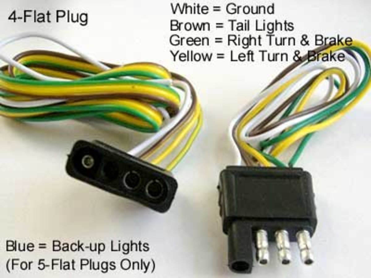
- White: Ground. This is the most critical connection. A bad ground will cause all sorts of problems.
- Brown: Tail/Running Lights. This powers the taillights on the trailer when your vehicle's headlights are on.
- Yellow: Left Turn Signal/Brake Light. This provides the signal for the left turn signal and also activates the brake light on the left side of the trailer when you apply the brakes.
- Green: Right Turn Signal/Brake Light. This provides the signal for the right turn signal and also activates the brake light on the right side of the trailer when you apply the brakes.
- Icons: Diagrams may use icons to represent components like fuses (a zigzag line in a box), lights (a circle with an "X" inside), and connectors (a rectangle with pins).
It's important to note that color codes can vary slightly between manufacturers and even model years. Always verify the wire functions with a multimeter before making any connections.
How It Works: The Electrical Flow
The 4-pin flat wiring system works by transferring electrical signals from your vehicle's lighting system to the trailer's lights. Here's the basic flow:
- Power Source: The vehicle's battery provides the power for the entire system.
- Lighting Switches: When you turn on your headlights, turn signals, or apply the brakes, the corresponding switches activate the circuits.
- Wiring Harness: The electrical signals are routed through the vehicle's wiring harness to the 4-pin flat connector.
- Connector Interface: The 4-pin flat connectors (vehicle and trailer sides) create a physical and electrical connection between the two vehicles.
- Trailer Lights: The electrical signals travel through the trailer's wiring harness to the appropriate lights, illuminating them as intended.
- Ground Return: The electrical current returns to the vehicle's battery through the ground wire, completing the circuit. A *good* ground is crucial.
When a pin is broken on the vehicle side connector, it interrupts this flow, causing the corresponding light(s) on the trailer to malfunction. For example, a broken ground pin will likely cause all the lights to flicker or not work at all.
Real-World Use: Troubleshooting Tips for a Broken Pin
So, you've got a broken pin. What do you do? Here’s a basic troubleshooting approach:
- Visual Inspection: Examine the connector for any signs of damage beyond the broken pin – corrosion, bent pins, cracked housing.
- Pin Identification: Determine which pin is broken. Is it the ground, running lights, or one of the turn signals?
- Temporary Fix (Use Caution!): If you absolutely *must* use the trailer immediately, and it's just a turn signal pin that's broken, *carefully* and *temporarily* try to make contact with the corresponding trailer-side pin. This is NOT a long-term solution and carries risk (see Safety below). A small piece of conductive metal inserted carefully might work, but monitor it closely for overheating.
- Replacement: The best solution is to replace the entire vehicle-side connector. These are relatively inexpensive and readily available at auto parts stores. Make sure to disconnect the vehicle's battery before starting this process!
- Wiring Repair: After replacing the connector, carefully inspect the wiring leading to the connector for any damage. Repair any frayed or corroded wires. Use proper crimping tools and heat shrink tubing for a secure and weather-resistant connection.
- Testing: Once the repair is complete, use a multimeter to verify that each pin is providing the correct voltage and signal when the corresponding lights are activated on the vehicle. Also, test the trailer lights to ensure they are working correctly.
If the broken pin is the ground pin, do *not* attempt a temporary fix. A faulty ground can cause serious electrical problems.
Safety Considerations
Working with electrical systems carries inherent risks. Here are some important safety precautions:
- Disconnect the Battery: Always disconnect the vehicle's negative battery terminal before working on any electrical circuits. This prevents accidental shorts and electrical shocks.
- Use Proper Tools: Use insulated tools designed for automotive electrical work.
- Avoid Working in Wet Conditions: Water and electricity are a dangerous combination.
- Fuse Protection: Ensure all circuits are properly fused. Never bypass a fuse with a higher amperage fuse, as this can overload the circuit and cause a fire.
- High-Risk Components: The vehicle's battery and the wiring harness connected to it are the most dangerous components. Handle them with extreme care. Avoid shorting the battery terminals. Be aware that some vehicles have airbags that can deploy if the electrical system is improperly handled.
- Temporary Fixes are Risky: As mentioned above, attempting temporary fixes, especially with a broken ground, can be very dangerous and lead to shorts, fires, or damage to your vehicle's electrical system.
- If in Doubt, Consult a Professional: If you are not comfortable working with electrical systems, it is best to consult a qualified mechanic.
By understanding the wiring diagram, following safe practices, and using proper troubleshooting techniques, you can confidently tackle trailer wiring repairs and modifications.
Now that you have a better understanding of 4-pin flat wiring and troubleshooting techniques, you're well-equipped to handle repairs and maintenance. Remember safety is paramount, and when in doubt, consult a professional. This knowledge empowers you to diagnose issues, make informed decisions, and potentially save money on repairs.
We have the detailed wiring diagram file referenced throughout this article. You can download it [hyperlink to the diagram file - replace with actual link] to use as a reference during your repairs. Good luck!