4 Pin Ignition Switch Wiring Diagram
Alright, let's dive into the often-overlooked but absolutely crucial world of the 4-pin ignition switch wiring diagram. If you're planning on tackling automotive electrical repairs, diagnosing starting issues, or even customizing your ride, understanding this diagram is paramount. It's your roadmap to the electrical heart of your vehicle's ignition system.
Purpose of Understanding the 4-Pin Ignition Switch Wiring Diagram
Why should you care? Simple: this diagram allows you to accurately diagnose problems with your starting system. Think about it – no start, intermittent starting issues, or even accessories behaving erratically can often be traced back to a faulty ignition switch or its wiring. Having this knowledge empowers you to:
- Troubleshoot Starting Problems: Pinpoint the exact cause of a "no crank" or "no start" condition.
- Perform Repairs: Replace a faulty ignition switch correctly and safely.
- Install Aftermarket Accessories: Connect accessories that require an ignition-switched power source (e.g., gauges, aftermarket stereos) without causing electrical chaos.
- Customize Your Vehicle: Understand the electrical system well enough to make modifications safely.
- Save Money: Avoid costly trips to the mechanic by diagnosing and fixing issues yourself.
Key Specs and Main Parts
A typical 4-pin ignition switch wiring diagram focuses on the switch itself and its immediate connections. The key components you'll encounter are:
- Ignition Switch: The mechanical switch activated by your key, controlling the flow of electricity to various circuits.
- Battery (B+) Terminal: The connection point for the direct power feed from the battery. This is typically a constant +12V supply.
- Ignition (IGN) Terminal: Provides power to the ignition system, fuel pump, and other engine management components when the key is in the "ON" or "RUN" position.
- Accessory (ACC) Terminal: Powers accessories like the radio, climate control, and power windows when the key is in the "ACC" or "ON" position.
- Start (STR) Terminal: Supplies power to the starter solenoid when the key is turned to the "START" position, engaging the starter motor.
- Fuses: Crucial safety devices located inline with each circuit to protect against overcurrents. Always check fuses first when troubleshooting.
- Relays: Electrically operated switches that control high-current circuits (like the starter) using a low-current signal from the ignition switch.
- Wiring Harness: The bundle of wires that connect the ignition switch to the rest of the vehicle's electrical system.
Symbols – Understanding the Diagram's Language
Deciphering the wiring diagram requires understanding the symbols used. Here's a breakdown:
- Solid Lines: Represent wires. The thickness of the line doesn't usually indicate wire gauge.
- Dashed Lines: May indicate shielding or grounding connections.
- Colors: Wires are color-coded (e.g., Red = Battery, Black = Ground). The diagram will include a legend explaining the color code. Always verify wire colors on your specific vehicle, as they can vary.
- Circles/Squares: Represent components like switches, fuses, relays, and connectors.
- Ground Symbol (Typically three downward-pointing lines): Indicates a connection to the vehicle's chassis ground.
- "B+" or "Battery" Symbol: Indicates a direct connection to the battery's positive terminal.
- Numerical Designations: Each wire and connector might have a number assigned. Consult your specific vehicle's wiring diagram for these designations.
How It Works: A Step-by-Step Explanation
The ignition switch acts as a gatekeeper, controlling the flow of electrical power to different circuits based on the key position:
- OFF: No circuits are energized. The key is removed, and no electrical power flows through the switch.
- ACC (Accessory): The battery (B+) terminal is connected to the Accessory (ACC) terminal, powering accessories like the radio and climate control. The Ignition (IGN) and Start (STR) terminals remain unpowered.
- ON (Ignition/Run): The battery (B+) terminal is connected to both the Ignition (IGN) and Accessory (ACC) terminals. This powers the engine management system, fuel pump, and other critical components, as well as the accessories. The Start (STR) terminal remains unpowered.
- START: The battery (B+) terminal is connected to the Ignition (IGN), Accessory (ACC), and Start (STR) terminals. This engages the starter motor, cranking the engine. Once the engine starts, the key should be released, returning the switch to the "ON" position. It's *critical* that the "START" circuit is only energized during cranking to prevent damage to the starter motor.
The ignition switch itself doesn't usually handle the full current load of the starter motor. Instead, it triggers a relay. When you turn the key to "START," the ignition switch sends a low-current signal to the relay. This signal activates the relay, which then closes a high-current circuit connecting the battery directly to the starter solenoid.
Real-World Use: Basic Troubleshooting Tips
Let's say your car won't start. Here's how the wiring diagram can help:
- "No Crank, No Start": Check the battery voltage. If the battery is good, test the voltage at the Battery (B+) terminal of the ignition switch. If there's no voltage, there's a problem with the battery cable or a blown fuse in the battery circuit.
- "Crank, No Start": Check that the Ignition (IGN) terminal receives power when the key is in the "ON" position. If not, the ignition switch may be faulty. Also, check the fuel pump relay and ignition system fuses.
- Accessories Don't Work: Check the Accessory (ACC) terminal for power when the key is in the "ACC" or "ON" position. A blown fuse in the accessory circuit is a common cause.
- Starter Doesn't Engage: Check the Start (STR) terminal for power when the key is turned to the "START" position. If there's power at the Start terminal, but the starter doesn't engage, the problem likely lies with the starter solenoid or the wiring between the ignition switch and the solenoid.
Always use a multimeter to test for voltage and continuity. Continuity testing verifies that a circuit is complete and unbroken.
Safety First! – Handling Risky Components
Working with automotive electrical systems can be dangerous. Here are some key safety precautions:
- Disconnect the Battery: Always disconnect the negative battery cable before working on the electrical system. This prevents accidental shorts and electrical shocks.
- Work in a Well-Ventilated Area: Batteries can produce explosive gases.
- Use Proper Tools: Use insulated tools designed for automotive electrical work.
- Be Mindful of Airbags: Some ignition circuits are related to airbag deployment. Consult your vehicle's service manual before working near airbag components.
- Double-Check Your Work: Before reconnecting the battery, carefully inspect your wiring to ensure everything is connected correctly and securely.
- Fuses Are Your Friends: Never replace a blown fuse with one of a higher amperage rating. This can overload the circuit and cause a fire.
Always consult your vehicle's specific wiring diagram. Generic diagrams provide a general overview, but the wiring configuration can vary significantly between makes and models. Having the correct diagram is crucial for accurate diagnosis and repair.
And remember, dealing with automotive electrical systems can be complex. If you're not comfortable with any of these procedures, it's always best to consult a qualified mechanic.
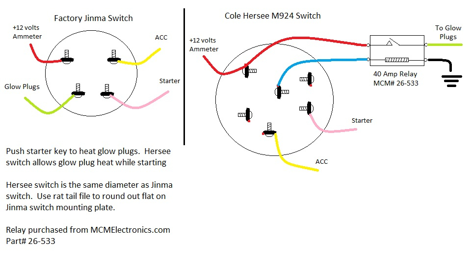
We have a generic 4-pin ignition switch wiring diagram available for download. This diagram provides a general overview and can be a helpful reference tool. However, remember to always consult your vehicle's specific wiring diagram for accurate information.