4 Pin Motorcycle Starter Relay Wiring Diagram
Alright, let's dive into the 4-pin motorcycle starter relay wiring diagram. Whether you're tackling a repair, customizing your ride, or just expanding your motorcycle electrical knowledge, understanding this diagram is absolutely crucial. It's the key to diagnosing starter problems and ensures you're not blindly poking around with a multimeter.
Purpose
Why bother with this diagram? Simple: your starter relay is a critical component in starting your motorcycle. A faulty relay can leave you stranded. Understanding the wiring diagram allows you to:
- Troubleshoot starting problems: Identify if the relay is the cause of your bike not starting.
- Perform repairs: Replace a faulty relay correctly.
- Customize your electrical system: Integrate aftermarket accessories that interact with the starting circuit.
- General electrical knowledge: Improve your understanding of motorcycle electrical systems.
Without a proper understanding, you risk misdiagnosis, incorrect repairs, or even damaging other components. This guide will help you avoid all that.
Key Specs and Main Parts
Let's break down the main components and their roles in the starting circuit:
- Battery: The power source for the entire electrical system, including the starter motor. Typically a 12V DC system.
- Ignition Switch: Controls the flow of power to various circuits, including the starter circuit when turned to the "start" position.
- Starter Button: A momentary switch that, when pressed, completes the circuit to activate the starter relay. Often referred to as the "start switch".
- Starter Relay (Solenoid): This is the heart of our discussion. It's an electromagnetic switch. A small current activates an electromagnet that closes a high-current circuit, connecting the battery directly to the starter motor. It's designed to handle the large amperage required to crank the engine.
- Starter Motor: The electric motor that physically turns the engine over to start it. Draws a significant amount of current.
- Wiring Harness: The network of wires that connect all the electrical components.
- Fuses: Crucial safety devices that protect the electrical system from overcurrent. A blown fuse indicates a problem that needs to be addressed, not just a fuse to be replaced blindly.
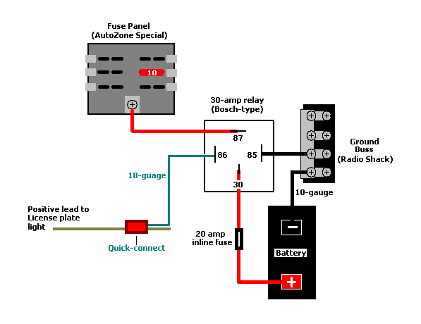
The 4 pins on the starter relay typically correspond to:
- Pin 30: Battery Positive (+) Input. This pin receives direct power from the battery.
- Pin 87: Starter Motor Output. This pin connects to the starter motor.
- Pin 85: Control Signal (Ground or Negative Trigger). This pin is connected to ground to activate the relay in some configurations.
- Pin 86: Control Signal (Positive Trigger). This pin receives a positive voltage signal from the start button.
Symbols
Understanding the symbols used in the wiring diagram is fundamental. Here's a breakdown of the common ones:
- Solid Lines: Represent wires. The thicker the line, generally the higher the current carrying capacity.
- Dashed Lines: May represent grounding connections or shielding.
- Battery Symbol: A series of long and short parallel lines, indicating the positive and negative terminals.
- Switch Symbol: A line that is broken to demonstrate the switch is open. The switch closes when engaged to complete the circuit.
- Relay Symbol: A coil (representing the electromagnet) and a switch (representing the high-current contacts).
- Ground Symbol: Usually looks like a downward-pointing triangle or a series of parallel lines getting smaller towards the bottom. Indicates a connection to the chassis, which serves as the return path for the electrical circuit.
- Fuse Symbol: Typically a zig-zag line encased in a rectangle.
- Colors: Wires are color-coded for identification. Common colors include red (positive), black (ground), blue, yellow, green, etc. Refer to your specific motorcycle's wiring diagram for its color code. Do not assume colors are standardized across all manufacturers.
A common notation is the wire gauge, indicated by a number followed by "AWG" (American Wire Gauge). A smaller AWG number indicates a thicker wire capable of carrying more current.
How It Works
Here's the step-by-step process of how the starter circuit functions:
- The ignition switch is turned to the "on" position, energizing various circuits.
- When the starter button is pressed, it sends a low-current signal (typically +12V) to pin 86 of the starter relay.
- Pin 85 of the relay is connected to ground. This creates a closed circuit for the relay coil.
- The current flowing through the relay coil creates an electromagnetic field.
- This electromagnetic field pulls the internal contacts of the relay together, closing the high-current circuit between pins 30 and 87.
- Battery power flows from pin 30, through the closed relay contacts, to pin 87, and then to the starter motor.
- The starter motor engages and cranks the engine.
- When the starter button is released, the low-current signal to the relay is interrupted, the electromagnetic field collapses, and the relay contacts open, disconnecting the starter motor.
Real-World Use – Basic Troubleshooting Tips
Here are some basic troubleshooting tips based on the wiring diagram:
- Bike won't start, no clicking sound:
- Check the battery voltage. Is it fully charged?
- Check the starter button and wiring leading to it. Is the signal getting to the relay's pin 86 when you press the button? Use a multimeter to verify.
- Check the ground connection to pin 85. Is it a solid connection?
- Check the fuse for the starter circuit. Is it blown? If so, replace it after identifying and resolving the underlying issue.
- Bike won't start, clicking sound from the relay:
- The relay is likely working (the click indicates the electromagnet is engaging), but it might not be making a good connection to the starter motor.
- Check the connections at pins 30 and 87 of the relay. Are they clean and tight?
- Check the wire between pin 87 and the starter motor. Is it damaged?
- The starter motor itself might be faulty.
- Continuously engaging starter:
- Sticking relay contacts. The relay needs to be replaced.
- Short circuit in the wiring to the relay.
Always use a multimeter to verify voltages and continuity. Don't rely on guesswork.
Continuity testing verifies that a circuit is complete and unbroken, allowing current to flow. Voltage testing verifies the presence of electrical potential at a specific point.
Safety
Working with motorcycle electrical systems can be dangerous. Here are some key safety precautions:
- Disconnect the battery: Always disconnect the negative terminal of the battery before working on the electrical system. This prevents accidental shorts and potential fires.
- Work in a well-ventilated area: Batteries can release hydrogen gas, which is flammable.
- Use insulated tools: Protect yourself from electric shock.
- Avoid working on a wet surface: Water conducts electricity.
- Be cautious around the starter motor: It draws a very high current, so avoid touching the terminals while the starting system is engaged.
- Fuses are critical. Never replace a fuse with one of a higher amperage rating. This bypasses the safety mechanism and could lead to a fire. Find the cause of the blown fuse instead.
The battery and the starter motor are the highest-risk components in this circuit due to the high amperage they handle. Exercise extreme caution when working with them.
With a solid grasp of this information, you're now well-equipped to understand and troubleshoot a 4-pin motorcycle starter relay wiring diagram.
We have the full diagram file, including component location guide and detailed wiring color, which is available for download.