
4 Pin Relay Wiring Diagram With Switch
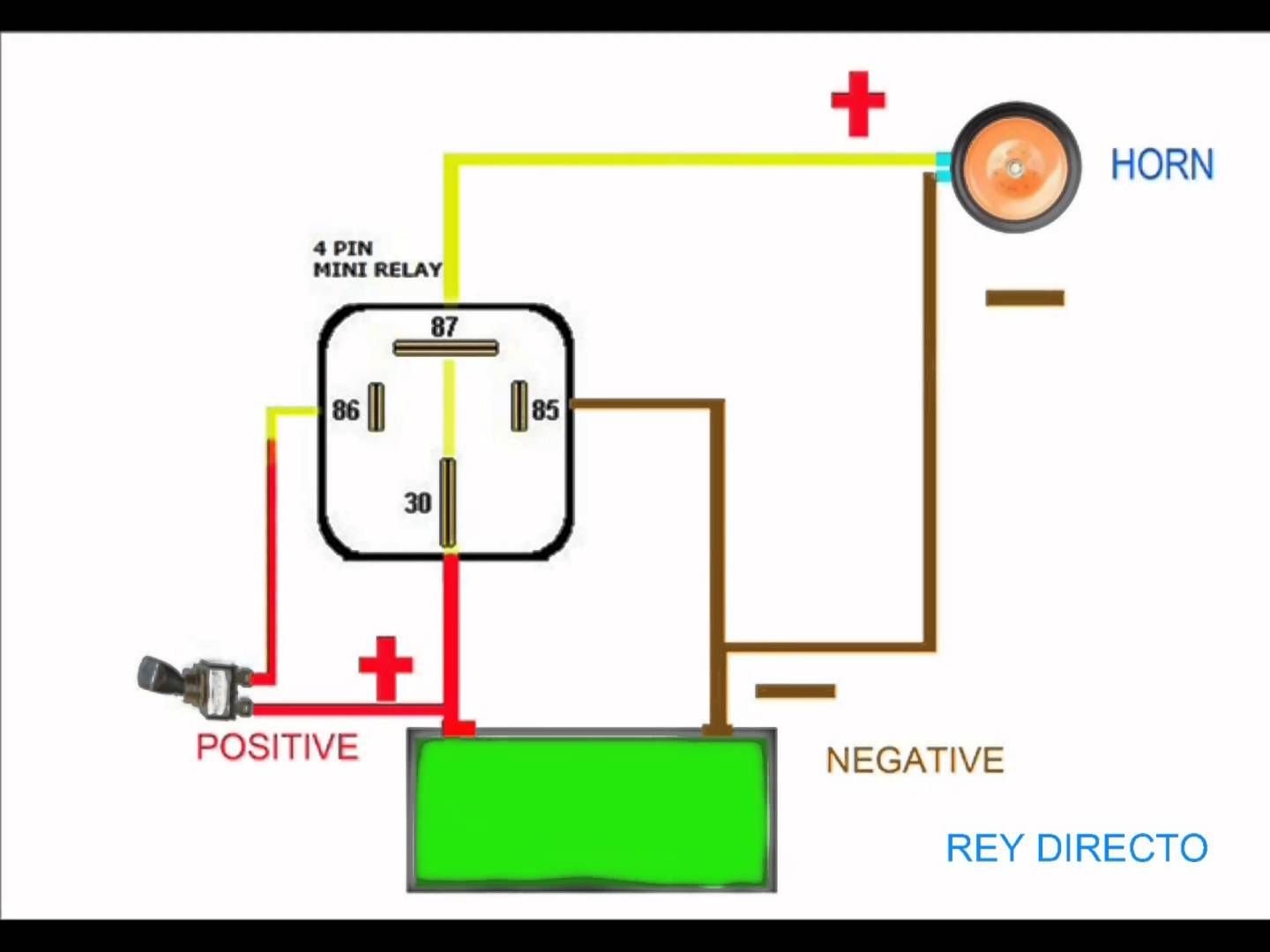
Alright, let's dive into the world of 4-pin relays and how to wire them up with a switch. This is a fundamental skill for anyone tinkering with automotive electrical systems, whether you're adding aftermarket accessories, diagnosing a problem, or just trying to understand how things work under the hood. This article will break down the wiring diagram, explain its components, and give you the knowledge to confidently tackle this kind of project.
Purpose of Understanding Relay Wiring
Why bother understanding this? Simple. Relays act as electrical switches controlled by a separate, lower-current circuit. This is crucial because many automotive circuits need to control high-power devices (like headlights, horns, or cooling fans) without overloading smaller switches or the wiring in your dashboard. Understanding the 4-pin relay wiring diagram lets you:
- Safely and effectively add aftermarket accessories.
- Diagnose electrical issues involving relays.
- Protect sensitive circuits from high current draw.
- Build custom circuits for specific applications.
Key Specs and Main Parts of a 4-Pin Relay Circuit
Let's look at the components involved in a typical 4-pin relay circuit with a switch:
- Relay: The heart of the system. A 4-pin relay consists of an electromagnet, a spring-loaded armature, and electrical contacts. When current flows through the electromagnet, it pulls the armature, closing (or opening) the contacts and completing the circuit for the high-power device.
- Switch: The user interface for activating the relay. This could be a simple toggle switch, a button, or even a signal from the vehicle's computer (ECU).
- Power Source (Battery): Supplies the necessary voltage (usually 12V in automotive applications) for both the relay's coil circuit and the switched circuit.
- Load (Device being controlled): This is the high-power device you're trying to control, like a headlight, horn, fog lights, or an electric fan.
- Wiring: The necessary conductors to connect everything together. Wire gauge (thickness) is critical to handle the current draw. Use appropriate sized wires (refer to your accessory's documentation for gauge recommendations).
- Fuse(s): Crucial for safety! Protect both the relay coil circuit and the switched circuit with appropriately sized fuses.
Decoding the 4-Pin Relay Wiring Diagram: Symbols and Colors
Understanding the symbols and conventions used in a wiring diagram is essential. Here’s a breakdown of common elements:
- Solid Lines: Represent wires. The thickness of the line *usually* indicates the gauge (thickness) of the wire, but always double-check the legend or accompanying notes.
- Dashed Lines: Often represent grounds or connections to the vehicle's chassis. Sometimes they indicate signal wires or control wires.
- Relay Symbol: Typically shown as a square or rectangle with internal markings indicating the coil and contact connections. The pins are usually labeled with numbers (85, 86, 30, 87) – we'll cover those in detail.
- Switch Symbol: Represents the physical switch used to activate the relay.
- Ground Symbol: A triangle or a series of horizontal lines diminishing in size, indicating a connection to the vehicle's chassis ground.
- Battery Symbol: Represents the power source (battery). Usually marked with + (positive) and - (negative).
- Fuse Symbol: A squiggly line inside a circle or rectangle, indicating a fuse.
Common Wire Colors: While not universal, certain wire colors are frequently used:
- Red: Typically used for positive (+) power connections.
- Black: Typically used for ground (-) connections.
- Blue/Yellow/White: Often used for signal wires or control wires. Always verify with a wiring diagram.
It is crucial to use a multimeter to verify voltage and continuity before connecting anything. Do not rely solely on wire colors. Use the correct wire gauge to prevent overheating and potential fires.
The 4-Pin Relay Pinout: Decoded
The most important aspect of a 4-pin relay is understanding the function of each pin. Here's the standard pinout:
- Pin 85: Relay Coil Ground. This pin connects to the vehicle's chassis ground.
- Pin 86: Relay Coil Positive. This pin connects to the switch and, eventually, to the positive (+) power source through a fuse. When the switch is closed, it provides power to the coil, energizing the relay.
- Pin 30: Common Input. This pin connects directly to the positive (+) power source through a fuse. This is the power source for the device you're controlling.
- Pin 87: Normally Open (NO) Output. This pin connects to the positive (+) side of the load (the device you're controlling). When the relay is *not* energized (switch is off), there is no connection between pins 30 and 87. When the relay *is* energized (switch is on), the connection is made, and power flows to the load.
How It Works: From Switch to Load
Here's a step-by-step explanation of how the circuit functions:
- Switch Off: With the switch open, no current flows to pin 86 (Relay Coil Positive). The relay coil is not energized. There is no connection between pins 30 and 87. The load (e.g., headlight) remains off.
- Switch On: When you close the switch, it completes the circuit, allowing current to flow from the positive (+) power source, through the fuse, through the switch, and into pin 86 (Relay Coil Positive).
- Relay Energized: The current flowing through the relay coil creates an electromagnetic field. This field pulls the armature, causing the contacts inside the relay to close.
- Circuit Completed: Closing the contacts inside the relay creates a connection between pin 30 (Common Input) and pin 87 (Normally Open Output).
- Load Activated: Current now flows from the positive (+) power source, through the fuse, into pin 30, through the closed relay contacts, out of pin 87, and to the positive (+) side of the load (e.g., headlight). The load is activated.
- Switch Off (Again): When you open the switch, the current to the relay coil is cut off. The electromagnetic field collapses, the armature returns to its original position, and the connection between pins 30 and 87 is broken, deactivating the load.
Real-World Use and Basic Troubleshooting
Let's say your fog lights aren't working. You've checked the bulbs, and they're good. Here's how to troubleshoot the relay circuit:
- Check the Fuse(s): Use a multimeter to verify continuity across the fuses in both the relay coil circuit and the switched circuit. Replace any blown fuses with the correct amperage rating.
- Verify Power and Ground: Use a multimeter to check for 12V at pin 30 with the ignition on. Also, confirm a good ground connection at pin 85.
- Test the Relay Coil: Remove the relay. Use a multimeter to measure the resistance between pins 85 and 86. A very low or very high resistance indicates a faulty coil. You can also apply 12V to pins 85 and 86 (observing proper polarity) to see if the relay "clicks," indicating it's energizing.
- Test the Switch: Use a multimeter to verify that the switch is functioning correctly. When the switch is closed, you should have continuity between its terminals.
- Check Wiring Connections: Inspect all wiring connections for corrosion, loose terminals, or damaged wires. Clean and tighten connections as needed.
Warning: Always disconnect the negative terminal of the battery before working on any electrical circuits.
Safety First!
Working with automotive electrical systems can be dangerous if proper precautions aren't taken.
- Always disconnect the negative terminal of the battery before working on any electrical circuits. This prevents accidental shorts and potential fires.
- Use appropriately sized fuses to protect circuits from overcurrent. Never use a fuse with a higher amperage rating than recommended.
- Use proper wiring techniques. Ensure all connections are secure and insulated to prevent shorts. Use heat shrink tubing or electrical tape to insulate connections.
- Be cautious when working near the battery. Batteries contain sulfuric acid, which can cause burns. Wear safety glasses and gloves.
- If you're unsure about any aspect of the wiring, consult a qualified mechanic or electrician. It's better to be safe than sorry.
Understanding the 4-pin relay wiring diagram and how it functions is a valuable skill for any automotive enthusiast. By following the steps outlined in this article and taking proper safety precautions, you can confidently troubleshoot and modify your vehicle's electrical system. We have a downloadable version of the wiring diagram readily available. Contact us for the diagram file to keep it handy for your projects.