4-pin To 5-pin Trailer Adapter Wiring Diagram
So, you're looking at adapting your vehicle's 4-pin trailer connector to a 5-pin configuration. Maybe you've upgraded your trailer and need that extra reverse light signal, or you're just tackling a repair. Understanding the wiring is crucial for safe and reliable towing. This article will walk you through the 4-pin to 5-pin trailer adapter wiring diagram, explaining the purpose, key components, and how it all works together.
Why This Diagram Matters
This isn't just about making lights blink; it's about safety and functionality. A correct wiring setup ensures:
- Proper Lighting: Tail lights, brake lights, turn signals, and, importantly, reverse lights all functioning as intended.
- Safe Towing: Incorrect wiring can lead to blown fuses, damaged electrical systems in your vehicle or trailer, and even fires.
- Compliance: Many jurisdictions require functional trailer lights for legal towing.
- Diagnosis and Repair: Knowing the wiring scheme makes troubleshooting electrical issues far easier. Imagine trying to find a short circuit without a map of the connections!
Whether you're performing routine maintenance, upgrading your trailer's functionality, or just learning about automotive electrical systems, mastering this wiring diagram is a valuable skill.
Key Specs and Main Parts
Before diving into the diagram, let's define the core components. We're dealing with two connectors:
- 4-Pin Connector: The standard flat connector commonly found on smaller trailers and vehicles. It provides connections for ground, tail lights, left turn/brake lights, and right turn/brake lights.
- 5-Pin Connector: Similar to the 4-pin but includes an additional pin for the reverse lights. This is often required for trailers with hydraulic surge brakes (where the reverse signal unlocks the actuator) or for general improved visibility when backing up.
The adapter itself is a relatively simple device, essentially re-routing the existing 4-pin signals and adding a wire specifically for the reverse lights. This wire typically needs to be tapped into the vehicle's reverse light circuit.
Key specs you might encounter include:
- Wire Gauge: Typically 16-18 gauge for lighting circuits. Using too thin a wire can lead to voltage drop and dim lights, while using too thick a wire is unnecessary.
- Voltage: The system operates at 12V DC (Direct Current).
- Current Capacity: Each circuit has a maximum current it can handle. Check your trailer's light specifications to ensure your vehicle's wiring and fuses can handle the load. Overloading a circuit will blow fuses and potentially damage wiring.
Understanding the Wiring Diagram Symbols
The diagram is your roadmap. Here's a breakdown of common symbols:
- Solid Lines: Represent wires. Thicker lines may indicate a thicker wire gauge, but always check the legend.
- Dashed Lines: Often represent wires that are optional or only present in certain configurations.
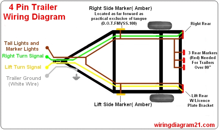
- Color Codes: Standard wire colors exist (e.g., brown for tail lights, yellow for left turn/brake), but they're not always followed. Always verify with a multimeter. Common trailer wiring colors are:
- White: Ground
- Brown: Tail Lights
- Yellow: Left Turn/Brake Lights
- Green: Right Turn/Brake Lights
- Blue: (5-pin only) Reverse Lights
- Connectors: Represented by squares or circles with lines leading to the wires. The pin numbers are usually indicated.
- Ground Symbol: Looks like an upside-down Christmas tree. Indicates a connection to the vehicle's chassis (ground).
A typical 4-pin to 5-pin adapter wiring diagram will show the following connections:
4-Pin Connector (Vehicle Side) --> 5-Pin Connector (Trailer Side)
- White (Ground) --> White (Ground)
- Brown (Tail Lights) --> Brown (Tail Lights)
- Yellow (Left Turn/Brake) --> Yellow (Left Turn/Brake)
- Green (Right Turn/Brake) --> Green (Right Turn/Brake)
- [Vehicle's Reverse Light Circuit] --> Blue (Reverse Lights)
The critical point is that the 5th pin (reverse light) is *not* automatically connected. You must tap into your vehicle's reverse light circuit and run a wire to the blue wire on the 5-pin connector.
How It Works
The adapter is a passive device, meaning it doesn't actively modify the electrical signals. It simply redirects the existing signals from the 4-pin connector to the corresponding pins on the 5-pin connector. The crucial addition is the dedicated wire for the reverse lights.
When you put your vehicle in reverse, the vehicle's reverse light circuit is energized. This 12V signal is then routed through the adapter's newly connected wire to the trailer's reverse lights, illuminating them.
The other circuits (tail lights, turn signals, brake lights) function as normal, with the adapter simply passing the signals through.
Real-World Use – Basic Troubleshooting Tips
Okay, you've wired everything up, but something isn't working. Here's a basic troubleshooting approach:
- Check Fuses: This is always the first step. Blown fuses are the most common culprit. Consult your vehicle's owner's manual to locate the relevant fuses.
- Test the Connections: Use a multimeter to verify that each pin on the 4-pin connector is providing the correct voltage when the corresponding function is activated (e.g., 12V on the yellow pin when the left turn signal is on).
- Grounding Issues: Poor grounding is a frequent problem. Ensure that the ground wire is securely connected to a clean, unpainted metal surface on both the vehicle and the trailer. Rust and corrosion can create resistance.
- Wire Continuity: Use a multimeter to check the continuity of each wire from the 4-pin connector to the 5-pin connector. This verifies that there are no breaks or shorts in the wiring.
- Reverse Light Tap: Double-check that you've tapped into the correct wire for the reverse lights. A wiring diagram specific to your vehicle is invaluable here. Use a test light or multimeter to confirm the wire is only energized when the vehicle is in reverse.
If you suspect a short circuit, a multimeter can also be used to measure the resistance between the wires and ground. A low resistance indicates a short, meaning electricity is taking an unintended path to ground.
Safety – Highlight Risky Components
Working with electrical systems can be dangerous. Here's what to watch out for:
- Battery Disconnect: Always disconnect the negative terminal of your vehicle's battery before working on any electrical wiring. This prevents accidental short circuits and electrical shocks.
- Wire Stripping: Use the correct size wire strippers to avoid damaging the conductors inside the wire. Damaged conductors can create weak points and increase resistance.
- Secure Connections: Use proper crimp connectors and heat shrink tubing to ensure secure and weather-resistant connections. Avoid using electrical tape as the sole means of insulation, as it can dry out and become ineffective over time.
- Overloading Circuits: Never exceed the current capacity of the wiring or the fuses. Doing so can lead to overheating and fires.
- Reverse Light Wire: Be very careful when tapping into the reverse light wire. Ensure you are connecting to the correct wire and that you are not accidentally grounding the circuit. This can damage your vehicle's electrical system. A wiring diagram and a multimeter are your best friends here.
Finally, remember to wear appropriate safety gear, including eye protection and gloves.
With a solid understanding of the wiring diagram and these safety precautions, you'll be well-equipped to tackle this project with confidence. We have a downloadable wiring diagram available to further assist you.