
4 Pin To 7 Pin Adapter Wiring Diagram
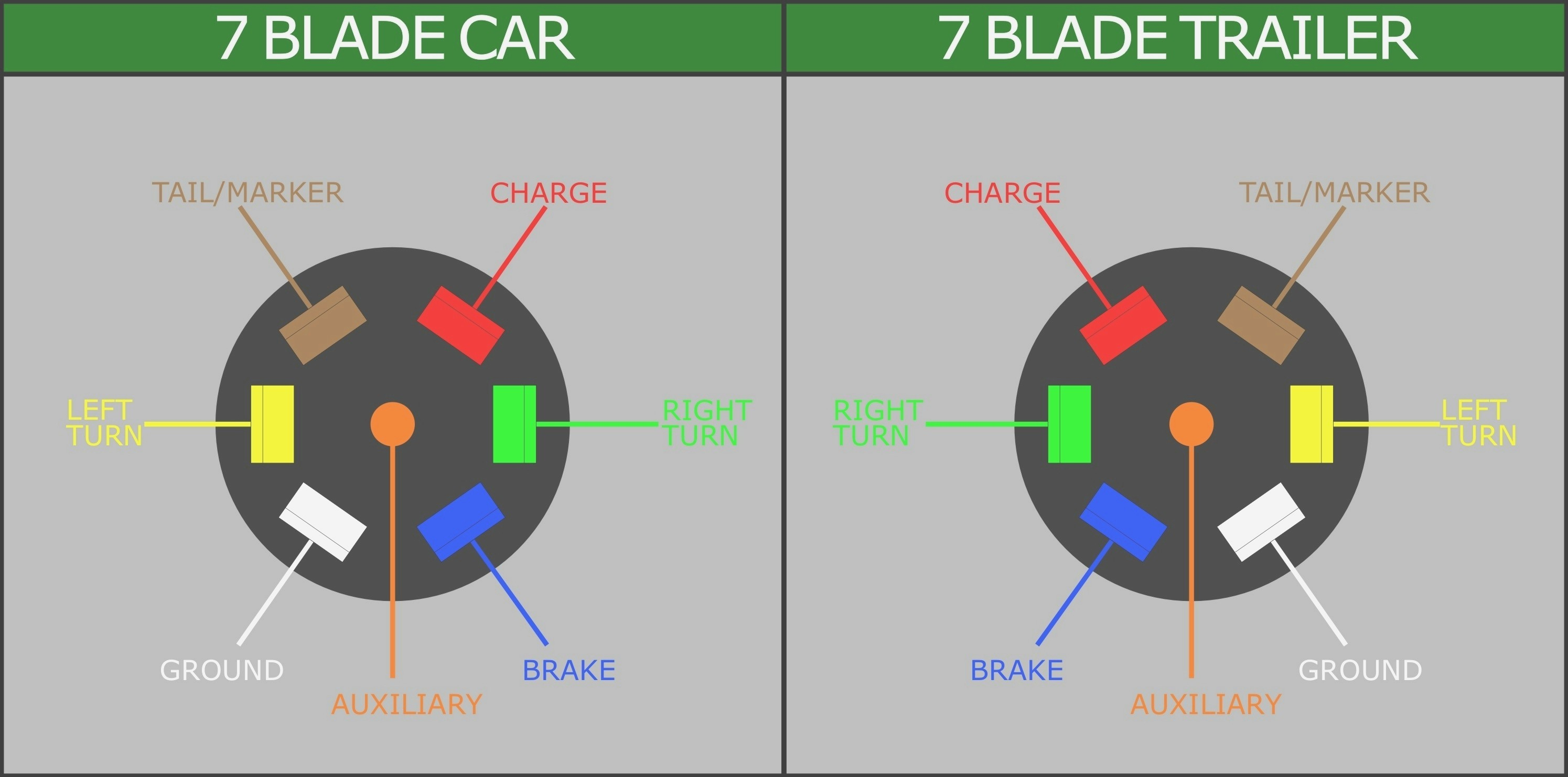
Alright, let's dive into the often confusing world of trailer wiring adapters, specifically the 4-Pin to 7-Pin variety. Whether you're adding electric brakes to your trailer, hooking up a camper with auxiliary power, or simply trying to decipher a wonky lighting setup, understanding this wiring diagram is crucial. This isn't just about plugging things in and hoping for the best; it's about safety, functionality, and preventing expensive damage to your vehicle's electrical system. We've got a detailed diagram available for download, but let's first break down the fundamentals.
Why This Diagram Matters
Imagine this scenario: You've just bought a used camper trailer with a standard 7-pin round connector. Your tow vehicle, however, is only equipped with the common 4-pin flat connector used primarily for basic trailer lights. Without an adapter and a proper understanding of the wiring, you're dead in the water. This diagram solves that problem. More than that, it's indispensable for:
- Repairing faulty wiring: Identifying broken or corroded wires is significantly easier with a visual guide.
- Adding new features: Upgrading your trailer with electric brakes or auxiliary power requires proper wiring knowledge.
- Troubleshooting electrical problems: A malfunctioning trailer light can often be traced back to a wiring issue.
- Understanding trailer electrical systems: Gaining a deeper understanding of how these systems work builds confidence and saves money on mechanic bills.
- Preventing damage: Incorrect wiring can fry fuses, damage control modules (especially on newer vehicles), and even cause fires.
Key Specs and Main Parts
Before we get to the diagram itself, let's clarify the key components involved.
Connectors: The Heart of the Matter
- 4-Pin Flat Connector: The most basic trailer connector, typically providing signals for:
- Ground (White): Provides a common ground for all circuits.
- Left Turn/Brake (Yellow): Powers the left turn signal and brake light on the trailer.
- Right Turn/Brake (Green): Powers the right turn signal and brake light on the trailer.
- Tail Lights (Brown): Powers the taillights and license plate light on the trailer.
- 7-Pin Round Connector (RV Blade Style): A more comprehensive connector offering additional functions:
- Ground (White): Similar to the 4-pin connector.
- Left Turn (Yellow): Powers the left turn signal.
- Right Turn (Green): Powers the right turn signal.
- Tail Lights (Brown): Powers the taillights.
- Electric Brakes (Blue): Activates the trailer's electric brakes (requires a brake controller in the tow vehicle).
- Reverse Lights (Black): Powers the trailer's reverse lights.
- Auxiliary Power (Red or Orange): Provides a 12V power source for charging the trailer battery or running appliances.
The Adapter: Bridging the Gap
The adapter itself is a simple device that converts the 4-pin signals to the corresponding pins on the 7-pin connector. However, it's important to note that the adapter does not magically create the missing functions. If your tow vehicle doesn't have a brake controller or a dedicated 12V auxiliary power line, the adapter alone won't provide those features. You'll need to install them separately and wire them appropriately.
Wiring Gauge (AWG): Important But Often Overlooked
The American Wire Gauge (AWG) specifies the thickness of the wire. For trailer wiring, using the correct gauge is crucial for safety and performance. For most lighting circuits, 16 AWG is sufficient. However, for electric brakes and auxiliary power, you'll typically want to use 12 or even 10 AWG, depending on the amperage draw. Consult your trailer and component manuals for the recommended wire gauge.
Symbols: Deciphering the Diagram
Wiring diagrams use standardized symbols to represent different components and connections. Here are some common symbols you'll encounter:
- Solid Lines: Represent wires. Thicker lines may indicate larger gauge wires.
- Dotted Lines: Often indicate optional or less critical connections.
- Circles or Dots: Represent connections between wires. A dot indicates a physical connection, while the absence of a dot where lines cross typically means they are not connected.
- Color Codes: Wires are often labeled with color codes (e.g., "WH" for white, "BK" for black, "YL" for yellow) to aid in identification. These color codes are, sadly, not always adhered to perfectly by manufacturers, so always double-check.
- Ground Symbol (Typically three horizontal lines decreasing in length): Indicates a connection to the vehicle's chassis ground.
How It Works: From 4 to 7
The basic principle is mapping the existing 4-pin functions to their corresponding 7-pin counterparts. Here's the typical wiring configuration:
- Ground (White): Connects directly to the ground pin on both the 4-pin and 7-pin connectors.
- Left Turn/Brake (Yellow): Connects to the left turn pin on the 7-pin connector. Crucially, the adapter uses the same wire for both brake and turn signals, which is common in 4-pin systems.
- Right Turn/Brake (Green): Connects to the right turn pin on the 7-pin connector. Again, shared brake and turn signal functionality.
- Tail Lights (Brown): Connects to the tail light pin on the 7-pin connector.
- Electric Brakes (Blue): This wire must be connected to a brake controller output from your tow vehicle. The adapter may have a wire for this, but it will only work if connected to a brake controller signal. This is where incorrect wiring is extremely dangerous and can lead to runaway trailers.
- Reverse Lights (Black): Requires running a separate wire from your vehicle's reverse light circuit to the 7-pin connector. The adapter may have a pigtail for this, but it needs to be connected to the correct source.
- Auxiliary Power (Red or Orange): Requires running a separate fused wire from your vehicle's battery to the 7-pin connector. This is a high-current circuit and should be properly fused to protect the wiring and battery.
Real-World Use: Basic Troubleshooting
Let's say your trailer lights aren't working correctly after installing the adapter. Here's a basic troubleshooting approach:
- Check the grounds: A poor ground connection is the most common cause of trailer light problems. Ensure both the trailer and tow vehicle have clean, secure ground connections to the chassis. Use a multimeter to test continuity between the ground pin on the connectors and the vehicle's chassis.
- Inspect the wiring: Look for damaged, corroded, or loose wires. Pay particular attention to connections made at the adapter and at the light fixtures themselves.
- Test the fuses: Blown fuses are another common culprit. Check the fuses in both the tow vehicle and the trailer (if equipped).
- Use a test light or multimeter: A test light can quickly check if a circuit is receiving power. A multimeter can provide more detailed information, such as voltage and resistance readings.
- Isolate the problem: Determine whether the issue is with the tow vehicle, the trailer, or the adapter itself. You can do this by testing the circuits independently.
Safety: Handle with Care
Working with electrical systems always carries inherent risks. Here are some key safety precautions:
- Disconnect the battery: Before working on any electrical wiring, disconnect the negative terminal of the tow vehicle's battery to prevent shorts and electrical shocks.
- Use proper tools: Use insulated tools designed for electrical work.
- Wear safety glasses: Protect your eyes from debris and potential sparks.
- Double-check your work: Before reconnecting the battery, carefully review your wiring to ensure it matches the diagram and is free of errors.
- Fuses are crucial: Always use the correct fuse rating for each circuit. Over-fusing can lead to overheating and fires. Never bypass a fuse.
- Electric brakes require professional attention if you are unsure: Faulty electric brake wiring can lead to serious accidents. If you're not comfortable working with electric brakes, seek professional help.
- High-current circuits (Auxiliary Power): Be extremely cautious when working with high-current circuits. Ensure the wiring is properly sized and fused to prevent overheating and fires.
This article provides a comprehensive overview of the 4-Pin to 7-Pin adapter wiring diagram. Remember to consult the specific documentation for your adapter and trailer, as wiring configurations can vary slightly. Now that you have a better understanding, you are better prepared. Don't hesitate to download the wiring diagram for detailed visual reference.