
4 Pole Starter Solenoid Wiring Diagram
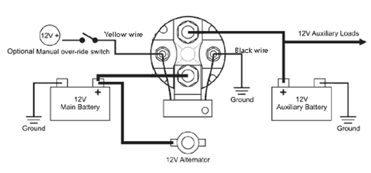
If you're diving into automotive electrical work, understanding a 4-pole starter solenoid wiring diagram is crucial. Whether you're diagnosing a no-start condition, upgrading your electrical system, or just expanding your automotive knowledge, this knowledge will give you a leg up. This article breaks down the intricacies of these diagrams, explaining the components, functionality, and troubleshooting tips, allowing you to confidently tackle related projects.
Purpose of Understanding the Wiring Diagram
Why bother learning this? Well, a 4-pole starter solenoid is a common component in many vehicles. Knowing how it's wired allows you to:
- Diagnose Starting Problems: Is your car failing to start? The wiring diagram helps you pinpoint the source of the problem (solenoid, wiring, or starter itself).
- Perform Repairs: Once you've identified the issue, you can use the diagram to correctly replace faulty wiring or the solenoid itself.
- Upgrade Your System: Maybe you're adding accessories or modifying your electrical system. Understanding the solenoid wiring helps you integrate these changes safely and effectively.
- Gain Knowledge: Even if you're not actively working on your car, understanding the basics improves your overall automotive knowledge and helps you communicate more effectively with professional mechanics.
Key Specifications and Main Parts
Let's define some key specs and the main components you'll encounter in a 4-pole starter solenoid wiring diagram:
- Solenoid: An electromechanical switch. When energized, it closes a high-current circuit to the starter motor. In a 4-pole solenoid, two small terminals (S & I) control the internal switch, and two larger terminals connect the battery and starter motor.
- Battery Terminal (B): This large terminal connects directly to the positive (+) terminal of the battery. It provides the main power source for the starter motor.
- Starter Terminal (S): This large terminal connects directly to the starter motor. When the solenoid is energized, it sends the battery's current to the starter motor, initiating the engine cranking process.
- "S" Terminal: A small terminal connected to the ignition switch. When the ignition key is turned to the "start" position, this terminal receives a low-current signal, energizing the solenoid.
- "I" Terminal: A small terminal that provides a 12V feed to the ignition coil during starting on older vehicles. This is sometimes referred to as the "ignition bypass" terminal. It’s not present in all 4-pole solenoids and is becoming increasingly less common on modern vehicles. Its purpose is to provide a full 12 volts to the ignition coil during cranking when the system voltage drops due to starter draw.
- Ground: A secure connection to the vehicle's chassis. This provides a return path for electrical current and is essential for proper circuit function. Some solenoids ground through the mounting bracket; others have a dedicated ground wire.
- Wiring Gauge: The thickness of the wires, measured in AWG (American Wire Gauge). Thicker wires (smaller AWG numbers) are needed for high-current circuits like the battery and starter connections.
- Voltage: Typically 12V DC in most automotive applications.
- Fuses and Relays: These protective devices are often included in the circuit to prevent damage from overcurrent or voltage spikes. The wiring diagram will show their location and rating.
Decoding the Symbols
Understanding the symbols used in the wiring diagram is essential for interpreting it correctly. Here's a breakdown of common elements:
- Solid Lines: Represent wires. Thicker lines generally indicate higher-current wires.
- Dashed Lines: May represent ground connections, shielded wires, or optional connections. Consult the diagram's key for specific meanings.
- Color Coding: Each wire is typically identified by a specific color (e.g., red for positive, black for ground). The diagram should include a color code chart. Common abbreviations include: BLK (black), RED (red), BLU (blue), GRN (green), YEL (yellow), WHT (white).
- Component Symbols: Symbols represent different electrical components:
- Solenoid: Often shown as a coil with a switch.
- Battery: Depicted as a series of short and long lines.
- Starter Motor: Typically shown as a circle with a motor symbol inside.
- Ignition Switch: Displayed as a switch with different positions (OFF, ACC, ON, START).
- Fuse: Represented as a squiggly line inside a rectangle.
- Relay: Shown as a coil and a switch, similar to the solenoid, but smaller.
- Numbers and Letters: These identify wire gauges, terminal numbers, or circuit designations.
How It Works
Here’s the sequence of events:
- Ignition Switch Activation: When you turn the ignition key to the "start" position, a low-current signal is sent to the "S" terminal of the solenoid.
- Solenoid Energization: The low-current signal energizes the solenoid's coil, creating an electromagnetic field.
- Switch Closure: The electromagnetic field pulls a plunger or lever inside the solenoid, closing a heavy-duty switch. This connects the Battery Terminal (B) directly to the Starter Terminal (S).
- Starter Motor Engagement: The high current from the battery flows through the closed switch to the starter motor, causing it to spin and engage the engine's flywheel, initiating the starting process. At the same time, on systems with an "I" terminal, power is sent to the ignition coil for enhanced starting.
- Releasing the Key: When you release the ignition key, it returns to the "run" position, disconnecting the signal to the "S" terminal.
- Solenoid Deactivation: The solenoid's coil de-energizes, and the switch opens, disconnecting the battery from the starter motor.
Real-World Use: Basic Troubleshooting
Here are some basic troubleshooting tips using the wiring diagram:
- No Click, No Start: If you turn the key and hear nothing, check the following:
- Battery Voltage: Ensure the battery is fully charged.
- "S" Terminal Voltage: Use a multimeter to check for voltage at the "S" terminal when the key is in the "start" position. If no voltage is present, the problem lies in the ignition switch or the wiring between the switch and the solenoid.
- Ground Connection: Ensure the solenoid has a good ground connection. Clean any corroded connections.
- Solenoid Itself: The solenoid might be faulty. Use a multimeter to check for continuity between the "B" and "S" terminals when the solenoid is energized. If there's no continuity, the solenoid needs replacement.
- Clicking Sound, No Start: If you hear a clicking sound but the engine doesn't crank, it could indicate:
- Weak Battery: The solenoid is engaging but doesn't have enough power to crank the starter.
- Poor Connections: Check and clean all connections, especially at the battery, starter motor, and solenoid terminals.
- Faulty Starter Motor: The starter motor itself might be drawing excessive current or have internal problems.
Safety First
Working with automotive electrical systems can be dangerous. Here are crucial safety precautions:
- Disconnect the Battery: Always disconnect the negative (-) battery terminal before working on any electrical components. This prevents accidental shorts and electrical shocks.
- Use Proper Tools: Use insulated tools designed for automotive electrical work.
- Wear Safety Glasses: Protect your eyes from sparks and debris.
- Be Aware of High-Current Circuits: The battery and starter circuits carry very high currents. Avoid shorting these circuits, as it can cause fires or damage to components.
- Work in a Well-Ventilated Area: When working with batteries, be aware of the potential for hydrogen gas buildup.
Remember, this information is for educational purposes and should be supplemented with your vehicle's specific service manual. Always consult a qualified mechanic if you're unsure about any procedure.
To help you further, we have a detailed 4-pole starter solenoid wiring diagram file available for download. This diagram provides a visual representation of the connections and can be a valuable tool when troubleshooting or performing repairs.