4 Pole Starter Solenoid Wiring Diagram Lawn Mower
Alright, let's dive into the wiring of a 4-pole starter solenoid on a lawn mower. This isn't exactly rocket science, but understanding the diagram is crucial for diagnosing electrical problems, performing repairs, and even modifying your mower for custom projects. Whether you're battling a stubborn engine or just want a better understanding of how your mower's starting system works, this guide will give you the knowledge you need.
Why This Diagram Matters
Imagine your lawn mower won't start. You've checked the fuel, the spark plug, and the battery seems fine. Chances are, the problem lies within the starting circuit, and the solenoid is a prime suspect. A wiring diagram is your roadmap. Without it, you're just poking around blindly, increasing the risk of damaging components or, worse, hurting yourself. Having a clear, understandable diagram allows you to:
- Diagnose Problems: Trace the circuit to pinpoint faulty components. Is the solenoid getting power? Is it switching the high-current path to the starter motor? The diagram helps you answer these questions systematically.
- Perform Repairs: Confidently replace damaged wiring, connectors, or the solenoid itself, knowing you're connecting everything correctly.
- Understand the System: Gain a deeper understanding of how the entire starting system works, from the key switch to the starter motor.
- Modify Your Mower: Want to add a remote starter or upgrade to a more robust solenoid? A wiring diagram is essential for planning and executing these modifications safely.
Key Specs and Main Parts
Before we dissect the diagram, let's identify the key components and their general specs. Keep in mind that specific values might vary depending on your lawn mower model, so always consult your mower's service manual for the most accurate information.
Main Parts:
- Battery: The heart of the electrical system, typically a 12V lead-acid battery. Amperage (Ah) ratings vary, but a higher Ah generally means more cranking power.
- Key Switch (Ignition Switch): Controls the flow of electricity to various circuits, including the starting circuit. It has multiple positions (Off, Run, Start).
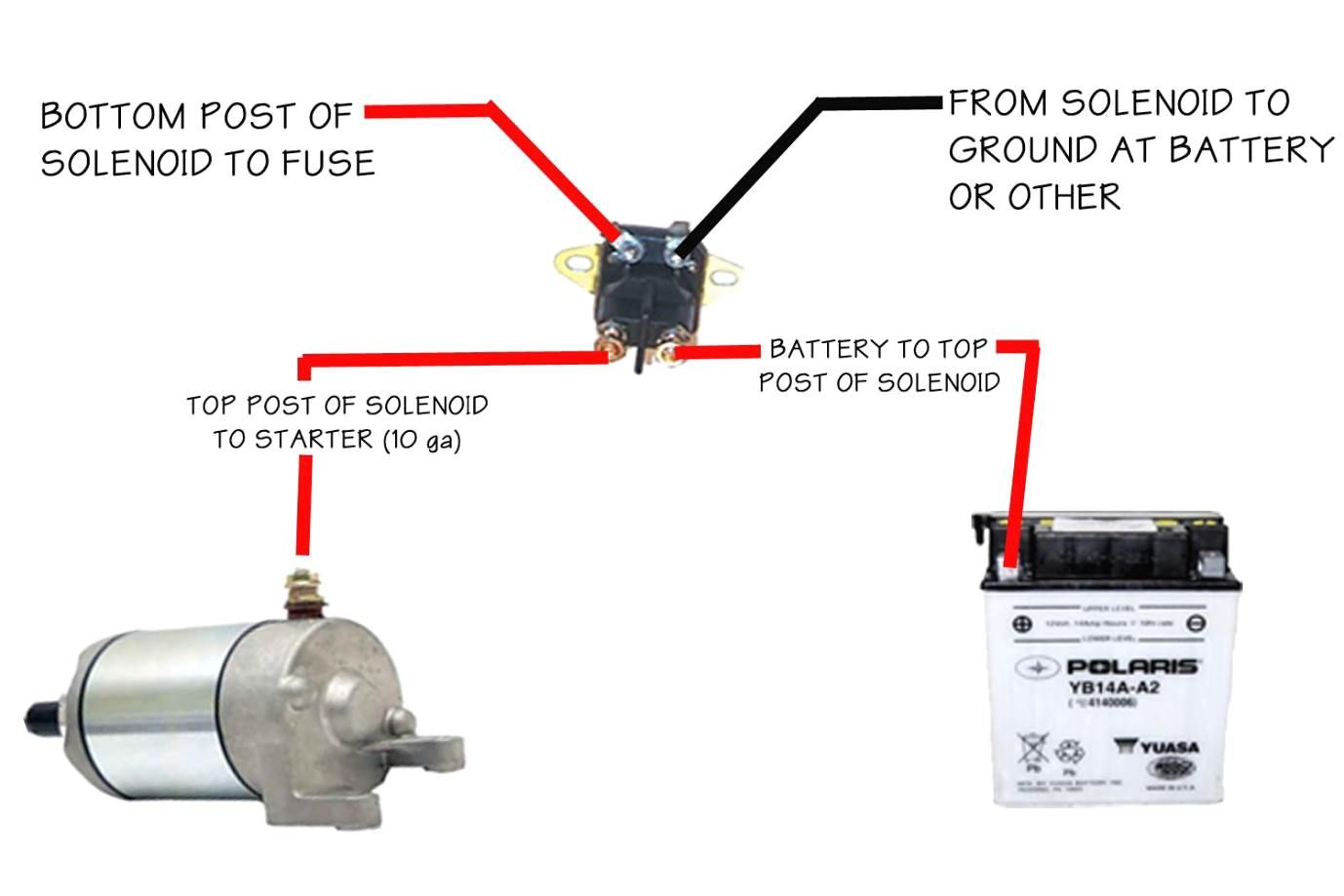
- Starter Solenoid (4-Pole): An electrically operated switch that handles the high current needed to crank the engine. A 4-pole solenoid has four terminals:
- Battery Terminal: Receives power directly from the battery (+).
- Starter Terminal: Connects to the starter motor (+).
- Control Terminal (S): Receives a low-current signal from the key switch to activate the solenoid.
- Ground Terminal: Provides a ground connection for the solenoid coil. Some solenoids are grounded through their mounting bracket, while others have a dedicated terminal.
- Starter Motor: An electric motor that spins the engine's flywheel to initiate combustion.
- Ground Connection (Chassis Ground): The negative (-) side of the battery is connected to the mower's frame, providing a common ground for all electrical components.
- Fuses/Circuit Breakers: Overcurrent protection devices that protect the wiring and components from damage in case of a short circuit.
Symbols: Deciphering the Diagram
A wiring diagram is a visual language, and understanding the symbols is key to interpreting it correctly. Here are some common symbols you'll encounter:
- Solid Lines: Represent wires. Thicker lines usually indicate wires that carry higher current.
- Dashed Lines: May represent internal connections within a component or optional wiring.
- Colors: Wires are often color-coded to help identify them. Common colors include red (positive), black (ground), and various other colors for signal wires (e.g., yellow for the solenoid control wire).
- Battery Symbol: A series of alternating long and short lines. The longer line represents the positive (+) terminal, and the shorter line represents the negative (-) terminal.
- Switch Symbol: A line broken by a pivoting arm. The position of the arm indicates whether the switch is open (circuit broken) or closed (circuit complete).
- Solenoid Symbol: Usually represented as a coil with a plunger or armature inside. The terminals are labeled (Battery, Starter, S, Ground).
- Motor Symbol: A circle with an "M" inside.
- Ground Symbol: Typically represented as a series of horizontal lines that decrease in length.
- Fuse/Circuit Breaker Symbol: Often represented as a zigzag line enclosed in a rectangle.
Understanding Wire Gauges: The gauge of a wire indicates its thickness and current-carrying capacity. Lower gauge numbers indicate thicker wires that can handle more current. For example, a 10-gauge wire is thicker and can handle more amperage than a 16-gauge wire. The starter motor circuit typically uses thicker wires (e.g., 10-gauge or 12-gauge) due to the high current demands.
How It Works: The Starting Sequence
Let's trace the flow of electricity through the starting circuit:
- Key Switch Activation: When you turn the key to the "Start" position, you complete a circuit that sends a low-current signal (typically 12V) to the control terminal (S) of the starter solenoid.
- Solenoid Activation: The low-current signal energizes the solenoid's coil, creating a magnetic field. This magnetic field pulls the solenoid's plunger or armature inward.
- High-Current Switching: As the plunger moves, it closes a heavy-duty switch inside the solenoid, connecting the battery terminal directly to the starter terminal. This allows a high current to flow from the battery to the starter motor.
- Starter Motor Cranking: The high current energizes the starter motor, causing it to spin the engine's flywheel, initiating the starting process.
- Releasing the Key: When you release the key, it returns to the "Run" position, cutting off the low-current signal to the solenoid. The solenoid de-energizes, the internal switch opens, and the starter motor stops cranking.
Real-World Use: Troubleshooting Tips
Here's how you can use the wiring diagram to diagnose common starting problems:
- No Cranking at All:
- Check the Battery: Ensure the battery is fully charged and the connections are clean and tight. Use a multimeter to check the battery voltage (should be around 12.6V when fully charged).
- Check the Key Switch: Use a multimeter to verify that the key switch is sending a signal to the solenoid's control terminal when in the "Start" position. If not, the switch may be faulty.
- Check the Solenoid: Use a multimeter to check for voltage at the solenoid's battery terminal. If voltage is present but the solenoid doesn't click when the key is turned, the solenoid itself may be faulty. You can also try bypassing the solenoid by carefully jumping the battery terminal to the starter terminal (use extreme caution!). If the starter motor cranks when you do this, the solenoid is definitely bad.
- Check the Starter Motor: If the solenoid clicks but the starter motor doesn't crank, the starter motor may be faulty or the connections to it may be loose or corroded.
- Check Fuses/Circuit Breakers: A blown fuse or tripped circuit breaker in the starting circuit can prevent the solenoid from receiving power.
- Solenoid Clicks But Engine Doesn't Crank:
- Check the Solenoid Contacts: The contacts inside the solenoid may be corroded or worn, preventing a good connection between the battery and starter motor.
- Check the Starter Motor: As mentioned above, the starter motor may be faulty.
Pro Tip: Always use a multimeter to check for voltage and continuity. A multimeter is an indispensable tool for diagnosing electrical problems.
Safety First: Respect the Electricity
Working with electrical systems can be dangerous if you're not careful. Here are some important safety precautions:
- Disconnect the Battery: Always disconnect the negative (-) battery cable before working on the electrical system. This prevents accidental shorts and sparks.
- Wear Safety Glasses: Protect your eyes from sparks and debris.
- Use Insulated Tools: Use tools with insulated handles to prevent electric shock.
- Avoid Working in Wet Conditions: Water is a conductor of electricity.
- Be Careful When Jumping the Solenoid: Bypassing the solenoid directly connects the battery to the starter motor. This can generate a lot of heat and sparks if done incorrectly. Only do this as a diagnostic test and be extremely careful.
- Replace Damaged Wiring: If you find any frayed, cracked, or burned wiring, replace it immediately.
Remember, the battery can deliver a lot of current very quickly. A short circuit can cause a fire or explosion.
With this information, you should be well-equipped to understand and troubleshoot the 4-pole starter solenoid wiring on your lawn mower. Remember to always refer to your mower's specific service manual for the most accurate information and diagrams. Stay safe, and happy tinkering!
We have the detailed 4-pole starter solenoid wiring diagram file available for download. Contact us, and we'll provide the download link.