
4-way To 7-way Trailer Wiring Diagram
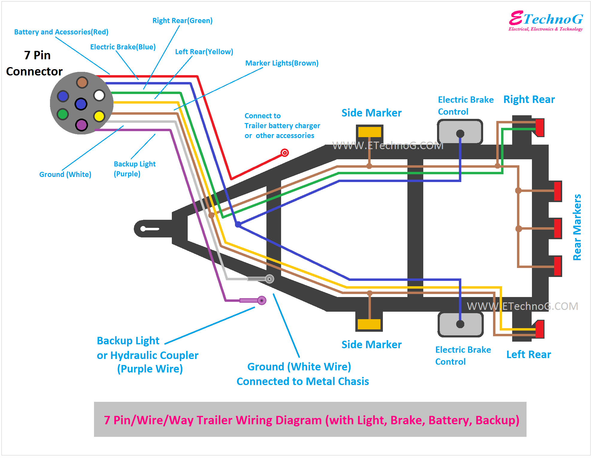
Alright, let's dive into the world of trailer wiring, specifically the ever-useful 4-way to 7-way conversion. This guide is designed for those of you already comfortable wrenching on your vehicles but need a clearer understanding of how these circuits work together. We're going to break down the 4-way to 7-way trailer wiring diagram, why it's important, and how to troubleshoot common issues. Think of this as your advanced guide to mastering trailer light connections.
Purpose and Why It Matters
Why bother with a 4-way to 7-way conversion? It all boils down to functionality. A standard 4-way connector, also known as a flat-4 connector, provides the bare minimum: running lights, brake lights, and turn signals (which are often combined on one wire). It's adequate for small utility trailers. However, as you move up to larger trailers – those with electric brakes, auxiliary power needs (like interior lights or a winch), or even reverse lights – the 7-way connector becomes essential. This diagram is vital for:
- Repairs: Diagnosing and fixing wiring problems on your trailer or tow vehicle.
- Upgrades: Converting from a basic 4-way setup to a more versatile 7-way.
- Custom Builds: Designing your own trailer wiring system from scratch.
- Learning: Gaining a deeper understanding of automotive electrical systems.
Understanding the wiring diagram prevents frustration, saves time, and, most importantly, ensures safety on the road.
Key Specs and Main Parts
Before we get into the diagram itself, let's define the key components and their specifications. Keep in mind that wire gauge (thickness) matters! Using too thin a wire can lead to voltage drop, overheating, and even fires. Consult your trailer and vehicle manuals for the appropriate wire gauge for each circuit.
- 4-Way Connector (Flat-4): Provides basic lighting functions. Typically uses 16-18 gauge wire.
- 7-Way Connector (RV Blade Style): Provides lighting, braking, auxiliary power, and reverse light functions. Typically uses 12-18 gauge wire depending on the circuit.
- Wiring Harness: A pre-made bundle of wires designed to connect the tow vehicle to the trailer. Simplifies installation and reduces the chance of errors.
- Electric Brake Controller: A device installed in the tow vehicle that allows the driver to control the electric brakes on the trailer. Essential for trailers equipped with electric brakes.
- Junction Box: A centralized location where wires are connected and protected from the elements.
- Fuses/Circuit Breakers: Protective devices that prevent damage from overcurrent situations. Always use the correct amperage rating.
- Relays: Electrically operated switches used to control high-current circuits with a low-current signal. Can be used to prevent overloading the tow vehicle's lighting circuits.
Symbols – Deciphering the Diagram
A wiring diagram uses symbols to represent different components and connections. Here's a breakdown of the common symbols you'll encounter:
- Solid Lines: Represent wires. The thickness of the line may indicate the wire gauge (thicker lines generally represent thicker wires).
- Dashed Lines: May represent optional connections or grounds.
- Color Codes: Each wire is typically identified by a color code. Common colors include:
- White: Ground
- Brown: Running Lights
- Yellow: Left Turn/Brake Light
- Green: Right Turn/Brake Light
- Blue: Electric Brakes
- Red: Auxiliary Power (12V+)
- Black: Reverse Lights (sometimes yellow or another color)
- Circles: Often represent connectors or junction points.
- Rectangles: Can represent various components like relays, fuses, or the brake controller.
- Ground Symbol (⏚): Indicates a connection to the vehicle's chassis, providing a return path for the electrical current.
Understanding these symbols is crucial for interpreting the wiring diagram and tracing circuits.
How It Works – The Flow of Electricity
The fundamental principle is simple: the tow vehicle's electrical system powers the trailer's lights and brakes. The 4-way to 7-way adapter, whether it’s a plug-in adapter or a hardwired conversion, essentially expands the capabilities of the tow vehicle's lighting system. Here’s a step-by-step breakdown:
- Basic Lighting (4-Way): The tow vehicle provides power to the running lights (brown wire), left turn/brake light (yellow wire), right turn/brake light (green wire), and ground (white wire).
- Adding Electric Brakes (Blue Wire): The electric brake controller in the tow vehicle sends a signal to the trailer's electric brakes via the blue wire. The amount of power sent depends on how hard the driver is braking. This requires a dedicated brake controller and wiring.
- Auxiliary Power (Red Wire): The red wire provides a constant 12V+ power source to the trailer. This can be used to charge a trailer battery, power interior lights, or operate other accessories. This is often fused separately and may require a heavier gauge wire.
- Reverse Lights (Black Wire): When the tow vehicle is shifted into reverse, the reverse light circuit is activated, sending power to the trailer's reverse lights via the black wire. This circuit often requires a relay.
- Grounding: The white wire provides a common ground for all circuits. A proper ground connection is absolutely essential for reliable operation.
The 7-way connector consolidates all these connections into a single, robust plug, making it easy to connect and disconnect the trailer. The wiring diagram illustrates how each wire from the tow vehicle connects to the corresponding wire on the trailer. It also shows the location of fuses, relays, and other components within the system.
Real-World Use – Troubleshooting Tips
Even with a solid understanding of the wiring diagram, problems can still arise. Here are some basic troubleshooting tips:
- No Lights At All: Check the tow vehicle's fuses. Also, verify the ground connection on both the tow vehicle and the trailer. A bad ground is the most common cause of lighting problems.
- One Light Not Working: Check the bulb first. Then, check the wiring connections for that specific circuit, looking for corrosion or loose connections. Use a multimeter to test for voltage at the bulb socket.
- Electric Brakes Not Working: Verify the brake controller is properly adjusted and functioning. Check the blue wire connection and the trailer's brake magnets. Use a multimeter to test for voltage at the brake magnets when the brake controller is activated.
- Blown Fuses: Indicates an overcurrent situation. Identify the cause of the overload (e.g., short circuit, faulty component) before replacing the fuse. Repeatedly blowing fuses is a sign of a serious problem.
- Corrosion: Clean all electrical connections with a wire brush and apply dielectric grease to prevent further corrosion.
When troubleshooting, always disconnect the trailer from the tow vehicle to prevent electrical shock or damage. Use a multimeter to test for voltage and continuity, and always follow the wiring diagram to ensure you're testing the correct circuits.
Safety – Handle with Care
Working with electrical systems involves inherent risks. Here are some safety precautions to keep in mind:
- Disconnect the Battery: Before working on any electrical wiring, disconnect the negative terminal of the tow vehicle's battery. This prevents accidental short circuits and electrical shock.
- Use Appropriate Tools: Use insulated tools designed for electrical work.
- Wear Safety Glasses: Protect your eyes from sparks and debris.
- Work in a Well-Ventilated Area: Avoid working in enclosed spaces where flammable fumes may accumulate.
- Be Careful with the 12V+ Auxiliary Power Wire: This wire is always hot (connected to the battery) and can cause a short circuit if it comes into contact with ground. Insulate the wire properly and avoid touching it to any metal surfaces.
The electric brake controller wiring can also be somewhat risky if not installed correctly. Always follow the manufacturer's instructions carefully and ensure the controller is properly grounded and fused.
Understanding the 4-way to 7-way trailer wiring diagram empowers you to maintain, repair, and upgrade your trailer's electrical system. By understanding the purpose of each wire, the symbols used in the diagram, and the potential hazards involved, you can tackle these tasks with confidence and ensure safe and reliable operation on the road. Remember to consult your vehicle and trailer manuals for specific wiring diagrams and recommendations. Happy towing!
We have the detailed wiring diagram file available for download, offering a visual aid to complement this guide. It is available upon request.