
4 Wire Ford Alternator Wiring Diagram
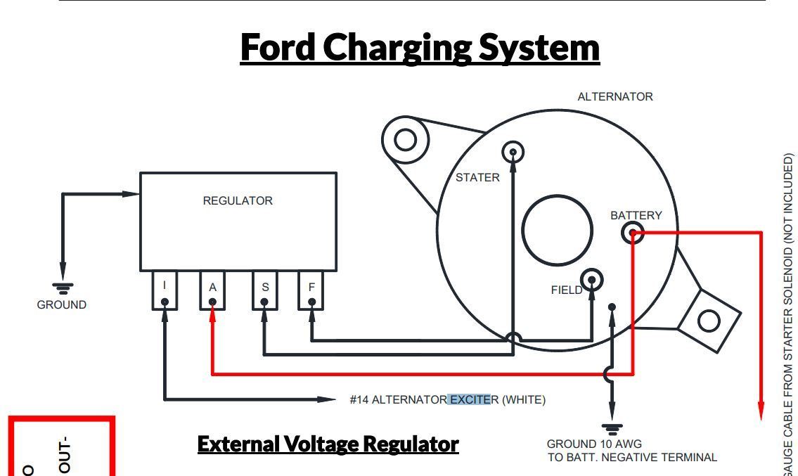
Understanding the 4-wire Ford alternator wiring diagram is crucial for anyone tackling electrical repairs, performance upgrades, or even just wanting to understand how their vehicle's charging system functions. This guide will break down the diagram in a clear, approachable way, even if you're not an electrical engineer. We'll cover everything from the purpose of each wire to basic troubleshooting, and remember, a detailed diagram is available for download – just ask! Proper understanding of the wiring is very important, especially when modifying a vehicle.
Why Bother Understanding the 4-Wire Ford Alternator?
The charging system is the heart of your vehicle's electrical system. A faulty alternator can lead to a dead battery, leaving you stranded. Knowing how the 4-wire Ford alternator works allows you to:
- Diagnose charging problems: Is your battery not charging? Understanding the wiring helps pinpoint the issue.
- Perform repairs confidently: Replace a damaged connector or wiring harness with assurance.
- Upgrade your charging system: If you're adding power-hungry accessories, you might need a higher-output alternator. Understanding the wiring is vital for a smooth swap.
- Gain a deeper understanding of your vehicle's electrical system: Knowledge is power! The more you know, the better equipped you are to maintain and modify your ride.
Key Specs and Main Parts
Before diving into the diagram, let's review the key components and specifications:
- Alternator: The generator that converts mechanical energy from the engine into electrical energy.
- Voltage Regulator: Controls the alternator's output voltage to protect the battery and electrical components. In 4-wire Ford alternators, the regulator is typically internal.
- Battery: Stores electrical energy and provides power to start the engine and operate accessories.
- Wiring Harness: A bundle of wires that connects the alternator to the battery, voltage regulator, and other electrical components.
- Fuses/Fusible Links: Safety devices that protect the circuit from overcurrent.
Common Ford Alternator Specs:
- Voltage Output: Typically 13.5-14.5 volts.
- Amperage Output: Varies widely, from 60 amps to over 200 amps depending on the application and vehicle options.
Decoding the 4-Wire Ford Alternator Wiring Diagram
The diagram itself uses standardized symbols and color codes to represent different wires and components. Here's a breakdown:
Symbols
- Solid Lines: Represent wires. The thickness of the line *may* indicate the wire gauge (thicker lines for higher current).
- Dashed Lines: Often represent ground connections.
- Circles: Can represent connectors or terminals.
- Rectangles: Can represent components like relays, fuses, or the voltage regulator (though the regulator is often internal).
- Alternator Symbol: A circle with three interlocking arcs inside.
- Battery Symbol: A series of long and short parallel lines, representing the battery's cells.
- Ground Symbol: Typically looks like an inverted triangle or a series of descending horizontal lines.
Color Codes
Ford uses standardized color codes for wiring. While these can vary slightly by year and model, some common ones include:
- Red: Typically indicates a direct connection to the battery (positive voltage).
- Black: Typically indicates a ground connection.
- White/Yellow, Green/Red, Blue/Red: Often used for the stator wires (we'll get to those in a moment) or voltage regulator signals. Refer to the specific diagram for your vehicle to confirm!
The 4 Wires Explained
Here's the critical part: understanding what each of those four wires does:
- Battery/Stator Output Wire (Heavy Gauge, Typically Red): This is the main output wire from the alternator, carrying the bulk of the charging current to the battery. It's usually a heavy-gauge wire because it handles high amperage. It connects directly (or via a fusible link) to the positive (+) terminal of the battery.
- Stator Wire (STA/S): This wire provides a signal to the voltage regulator based on the alternator's output. The voltage regulator uses this data to adjust the magnetic field on the rotor (spinning part of the alternator). Its value changes as engine RPM changes.
- Ignition/Voltage Sense Wire (I/A): This wire provides a switched 12V+ source when the ignition is on. It "tells" the voltage regulator when the engine is running and to begin charging. This line is usually connected to a fuse or a fuse tap that provides power when the ignition is on. It also acts as voltage sensing wire where the voltage regulator uses this signal to compensate voltage drop.
- Ground Wire (Typically Black): Provides a direct connection from the alternator case to the vehicle chassis, ensuring a good electrical ground. This is critical for proper operation.
How It Works: A Simplified Explanation
The alternator works by spinning a rotor inside a stator. The rotor has electromagnets while stator is coiled wire. As the rotor spins inside the stator, it induces an alternating current (AC) in the stator windings. This AC current is then converted to direct current (DC) by a rectifier (usually a set of diodes) inside the alternator.
The voltage regulator controls the amount of current flowing through the rotor windings. By adjusting the rotor current, the regulator controls the strength of the magnetic field, and therefore the output voltage of the alternator. The voltage regulator monitors both the voltage at the battery (through the sense wire) and the output of the stator (through the stator wire) to determine how much current to send to the rotor.
Real-World Use: Basic Troubleshooting
Here are a few basic troubleshooting steps you can take using your understanding of the wiring diagram:
- Battery Not Charging: Check the battery voltage with the engine running. It should be around 13.5-14.5 volts. If it's lower, check the main output wire (red) for voltage drop. Also, verify the ignition wire (I/A) is receiving power when the ignition is switched on.
- Overcharging (High Voltage): This is often a sign of a faulty voltage regulator. Double-check the wiring to the voltage regulator, particularly the sense wire. If the wiring is good, the regulator (or the entire alternator if the regulator is internal) likely needs replacement.
- No Output: Verify the ground wire is securely connected to the chassis. A poor ground can cause all sorts of issues. Next, check the fuses related to the alternator circuit.
Safety First!
Working with automotive electrical systems can be dangerous. Here are some important safety precautions:
- Disconnect the battery: Always disconnect the negative (-) battery terminal before working on any electrical components. This prevents accidental shorts and electrical shocks.
- Use insulated tools: Use tools with insulated handles to prevent electrical shock.
- Avoid working in wet conditions: Water is a conductor of electricity.
- Be careful around the alternator output wire: This wire carries high current and can cause severe burns if shorted to ground. Always disconnect the battery before working on this circuit!
- Double-check your wiring: Mistakes in wiring can damage electrical components. Refer to the wiring diagram carefully.
- If you're unsure, consult a professional: It's always better to be safe than sorry. If you're not comfortable working on your car's electrical system, take it to a qualified mechanic.
Understanding the 4-wire Ford alternator wiring diagram empowers you to diagnose, repair, and upgrade your vehicle's charging system with confidence. Take your time, follow the diagram closely, and always prioritize safety.
Remember, we have a detailed 4-wire Ford alternator wiring diagram available for download. Just let us know, and we'll provide you with the link.