4 Wire Idle Air Control Valve Wiring Diagram
Alright, let's dive into the world of 4-wire Idle Air Control (IAC) valves. Whether you're battling a surging idle, tackling an engine swap, or just expanding your automotive knowledge, understanding the IAC valve wiring diagram is crucial. This guide will break down the intricacies, equipping you with the knowledge to diagnose, repair, and even modify your engine's idle control system. We'll cover everything from the basic purpose to real-world troubleshooting, all while prioritizing safety.
Why This Diagram Matters
The IAC valve plays a vital role in maintaining a stable idle speed, regardless of engine load or temperature. A malfunctioning IAC valve can lead to a host of issues, including:
- Stalling: Especially at idle or when coming to a stop.
- Surging Idle: The engine RPM fluctuating erratically.
- High Idle: The engine idling at a higher-than-normal RPM.
- Poor Fuel Economy: An improperly controlled idle can waste fuel.
- Check Engine Light (CEL): Diagnostic trouble codes related to the IAC circuit.
Having a firm grasp of the 4-wire IAC wiring diagram allows you to:
- Accurately diagnose IAC valve problems.
- Perform targeted repairs and avoid unnecessary parts replacements.
- Understand the electrical signals controlling the IAC.
- Modify your engine management system safely and effectively (if applicable).
- Trace wiring faults within the IAC circuit.
Key Specs and Main Parts
Before we jump into the wiring, let's define the key components involved. The IAC valve itself is an electromechanical device, and its operation relies on precise electrical signals. The core components are:
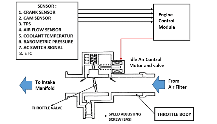
- IAC Valve: The electromechanical actuator that controls the amount of air bypassing the throttle plate at idle. Inside, you'll usually find a stepper motor or a solenoid, responsible for moving a pintle or plunger that regulates airflow.
- Engine Control Unit (ECU): The "brain" of the engine management system. The ECU receives inputs from various sensors (like engine coolant temperature, throttle position, and vehicle speed) and calculates the appropriate IAC valve position to maintain the desired idle speed. It then sends the control signals to the IAC.
- Wiring Harness: The bundle of wires connecting the IAC valve to the ECU and the vehicle's power and ground.
- Connectors: The physical plugs that join the IAC valve to the wiring harness.
Here are some common 4-wire IAC valve specifications:
- Voltage: Typically operates on a 12V DC system.
- Resistance: Each coil within the IAC valve (two coils in a 4-wire system) will have a specific resistance, usually measured in ohms (Ω). This is important for testing the integrity of the valve. Refer to your vehicle's service manual for the correct resistance values.
- Signal Type: The ECU sends pulse-width modulated (PWM) signals to control the position of the IAC valve. PWM means that the ECU rapidly switches the voltage on and off, varying the proportion of time the voltage is "on" (the duty cycle) to adjust the valve position.
Symbols – Lines, Colors, and Icons
Understanding the symbols in the wiring diagram is essential for interpreting it correctly. Here's a breakdown:
- Lines: Represent wires. Thicker lines often indicate wires carrying higher current.
- Colors: Each wire is designated a specific color, typically abbreviated (e.g., BLK for black, RED for red, GRN for green). Color coding helps you identify and trace wires within the harness. Use a wiring diagram key or legend to identify the meaning of each color code.
- Icons: Represent electrical components. Common icons include:
- Resistor: A zig-zag line.
- Ground: A series of downward-pointing lines, often resembling a Christmas tree.
- ECU: Usually a rectangular box labeled "ECU" or "PCM" (Powertrain Control Module).
- Connector: A circle or square with an arrow pointing into it, indicating where wires connect.
- IAC Valve: May be represented by a simplified schematic of the valve's internal components (e.g., a stepper motor with coils).
- Numbers/Letters: Wires and connector pins are often labeled with numbers or letters to identify their specific function.
How It Works
The 4-wire IAC valve typically uses a stepper motor with two coils. Here's how it works:
- ECU Control: The ECU monitors engine parameters and determines the required idle airflow.
- PWM Signals: The ECU sends two PWM signals to the IAC valve, one for each coil in the stepper motor. These signals control the direction and amount of rotation of the motor.
- Stepper Motor Action: The PWM signals energize the coils in a specific sequence, causing the stepper motor to rotate in small steps.
- Pintle/Plunger Movement: The stepper motor's rotation moves a pintle or plunger inside the IAC valve, opening or closing an air passage that bypasses the throttle plate.
- Airflow Adjustment: By controlling the position of the pintle or plunger, the IAC valve precisely regulates the amount of air entering the engine at idle, maintaining the desired RPM.
- Feedback (Indirect): The ECU monitors the engine speed. If the speed is too high, the ECU closes the valve; if the speed is too low, the ECU opens the valve. This continues until the correct idle speed is reached.
Real-World Use – Basic Troubleshooting Tips
Here are some basic troubleshooting steps you can perform using the wiring diagram and a multimeter:
- Visual Inspection: Check the IAC valve connector for corrosion, damaged wires, or loose connections. Repair or replace as needed.
- Resistance Test: Disconnect the IAC valve connector and use a multimeter to measure the resistance across each coil. Compare your readings to the specifications in your vehicle's service manual. Infinite resistance indicates an open circuit, while very low resistance indicates a short circuit.
- Voltage Test: With the ignition on and the IAC valve connected, use a multimeter to check for voltage at the power wires of the IAC valve connector. You should see approximately 12V. No voltage indicates a problem in the wiring harness or a faulty fuse or relay.
- Continuity Test: Use a multimeter to check for continuity between the ground wires of the IAC valve connector and a known good ground point on the vehicle's chassis. No continuity indicates a broken or disconnected ground wire.
- Scan Tool Diagnostics: Use an OBD-II scan tool to read any diagnostic trouble codes (DTCs) related to the IAC circuit. The DTCs can provide valuable clues about the nature of the problem.
Example: Let's say you have a P0505 DTC (Idle Air Control System Malfunction). After visually inspecting the wiring and connector, you perform a resistance test on the IAC valve. You find that one of the coils has infinite resistance. This indicates an open circuit within the IAC valve, likely requiring replacement of the valve.
Safety – Highlight Risky Components
Working on automotive electrical systems involves inherent risks. Always disconnect the negative battery cable before performing any electrical work. Here's what to watch out for:
- Short Circuits: Damaged or frayed wires can cause short circuits, which can damage electrical components and even start a fire. Inspect wiring carefully and repair any damage.
- High Current: Some circuits carry high current, which can be dangerous if you accidentally create a short circuit. Always use a multimeter with appropriate voltage and current ratings.
- Airbag System: Be extremely careful when working near airbag system components. Accidental deployment of an airbag can cause serious injury. Consult your vehicle's service manual for proper airbag deactivation procedures.
- Fuel System: The IAC valve is often located near the fuel system. Ensure there are no fuel leaks before working in this area. Fuel vapors are highly flammable.
Important Note: Never probe wires directly with sharp objects, as this can damage the insulation and create a short circuit. Use back-probing techniques (inserting the multimeter probe into the back of the connector without piercing the wire) whenever possible.
With this information, you’re now equipped to understand and work on your 4-wire IAC valve system. Remember to consult your vehicle's specific wiring diagram and service manual for accurate and detailed information. And always prioritize safety.
We have a detailed 4-Wire IAC Valve Wiring Diagram file available for download. This resource will give you a visual aid for diagnosing and repairing your idle control system. Please contact us to request the diagram.