
4 Wire Mitsubishi 4 Pin Alternator Wiring Diagram
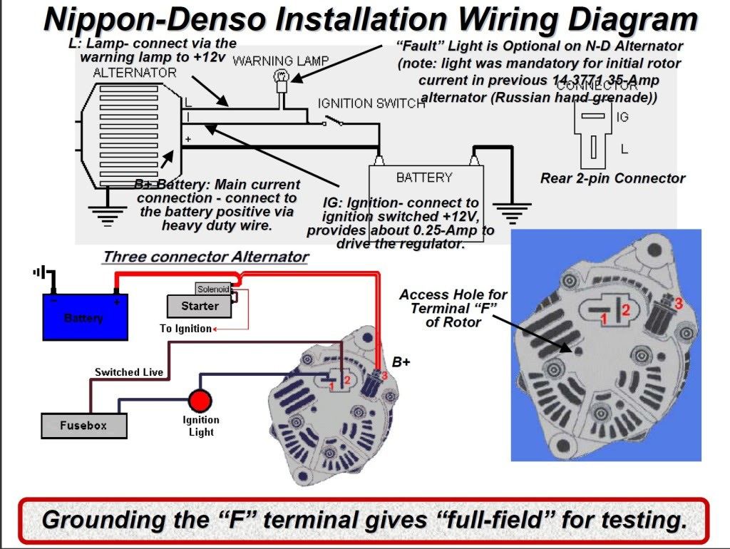
Alright, let's dive into the world of 4-wire Mitsubishi 4-pin alternator wiring. This isn't just about connecting wires; it's about understanding how your charging system works, diagnosing potential problems, and even upgrading your vehicle's electrical capabilities. Whether you're chasing down a mysterious battery drain, swapping an engine, or simply want to gain a deeper understanding of your car's electrical heart, this guide is for you. We'll break down the wiring diagram, explain the components, and give you some practical troubleshooting tips.
Purpose of Understanding the Diagram
Why bother learning this? Several reasons. First, for repairs. Diagnosing charging issues without a clear understanding of the wiring is like searching for a needle in a haystack. Second, for modifications. If you're adding electrical accessories like a high-powered audio system or auxiliary lighting, you need to ensure your charging system can handle the increased load. Understanding the alternator wiring allows you to determine its capacity and make necessary upgrades. Third, for general knowledge. Being able to understand and interpret electrical diagrams empowers you to perform your own maintenance and repairs, saving you money and giving you a greater sense of control over your vehicle.
Key Specs and Main Parts
Let's get familiar with the components we'll be dealing with:
- Alternator: The heart of the charging system. It converts mechanical energy from the engine into electrical energy to charge the battery and power the vehicle's electrical systems.
- Battery: Stores electrical energy and provides power to start the engine and operate electrical accessories when the engine isn't running.
- Voltage Regulator: A critical component that controls the alternator's output voltage, preventing overcharging and damage to the battery and electrical system. It's often integrated inside the alternator on modern units.
- Ignition Switch: Controls the flow of power to various circuits in the vehicle, including the alternator's exciter circuit.
- Wiring Harness: The network of wires that connects all the electrical components.
- Fuses: Safety devices that protect circuits from overcurrent.
A typical 4-wire Mitsubishi 4-pin alternator setup uses the following connections:
- B+ (Battery Positive): This is the heavy-gauge wire that connects directly to the positive terminal of the battery. It carries the main charging current.
- S (Sense): This wire is used by the voltage regulator to sense the battery voltage at the battery itself. This allows the regulator to compensate for voltage drops in the wiring and ensure the battery is properly charged. It is also sometimes called a "remote sense" wire.
- L (Lamp/Indicator): This wire connects to the charging system indicator lamp in the instrument cluster. It provides a ground path to illuminate the lamp when the alternator isn't charging properly. When the alternator is charging, it supplies a voltage on this wire, extinguishing the lamp.
- IG (Ignition): This wire provides a 12V+ signal from the ignition switch when the key is in the "on" or "run" position. This "excites" the alternator, telling it to start charging. It's also called a "trigger" wire.
Symbols in the Wiring Diagram
Understanding the symbols in the wiring diagram is crucial for interpreting it correctly. Here's a breakdown of common symbols:
- Solid Lines: Represent wires. The thickness of the line often indicates the wire gauge (thicker lines = larger gauge = higher current capacity).
- Dashed Lines: May represent shielded wires or connections to ground.
- Circles: Often represent connectors or terminals.
- Squares: Can represent fuses, relays, or other electrical components.
- Ground Symbol (usually three horizontal lines decreasing in size): Indicates a connection to the vehicle's chassis, which serves as the electrical ground.
Colors: Wiring diagrams use color codes to identify wires. While the exact color coding can vary between manufacturers and models, some common colors include:
- Red: Typically used for power (12V+).
- Black: Typically used for ground.
- Blue: Often used for lighting circuits.
- Yellow: Can be used for various functions.
- Green: Commonly used for sensors or signals.
Always refer to the specific wiring diagram for your vehicle to confirm the color coding.
How It Works
Here's a simplified explanation of how the 4-wire Mitsubishi 4-pin alternator system functions:
- Ignition On: When you turn the ignition switch to the "on" position, the IG wire receives 12V+. This signals the alternator to prepare for charging.
- Starting the Engine: As the engine starts and the alternator begins to spin, a small current flows through the L wire to ground via the charging system indicator lamp in the instrument cluster. This completes the circuit and illuminates the lamp.
- Alternator Charging: As the alternator speed increases, it begins to generate voltage. This voltage on the L wire overcomes the ground path through the indicator lamp, extinguishing the lamp. This indicates that the alternator is charging.
- Voltage Regulation: The voltage regulator monitors the battery voltage via the S (sense) wire. If the battery voltage is low, the regulator increases the alternator's output. If the battery voltage is high, the regulator decreases the alternator's output. This maintains a stable charging voltage, typically around 13.8-14.4 volts.
- Battery Charging: The alternator's output current flows through the B+ wire to the battery, replenishing the energy used to start the engine and power the electrical system.
Real-World Use: Basic Troubleshooting Tips
Here are some common troubleshooting scenarios and how the wiring diagram can help:
- Charging System Indicator Lamp Stays On: This usually indicates a problem with the alternator, voltage regulator, or wiring. Check the B+ wire for proper connection and voltage. Verify that the L wire is properly connected and that there are no shorts to ground. A faulty voltage regulator (often internal to the alternator) is a common culprit.
- Battery Not Charging: Check the B+ wire for proper voltage output from the alternator (with the engine running). Ensure the S wire is properly connected and sensing the correct battery voltage. A blown fuse in the IG circuit can prevent the alternator from being excited.
- Overcharging (Battery Boils): This usually indicates a faulty voltage regulator. The regulator isn't properly controlling the alternator's output, resulting in excessive voltage being applied to the battery. Check the S wire for a poor connection, as this can cause the regulator to misinterpret the battery voltage.
- Battery Drain: While not directly related to the alternator charging circuit, a faulty diode inside the alternator can sometimes cause a battery drain when the engine is off. Disconnecting the alternator (B+ wire) can help isolate this issue.
Using a Multimeter: A multimeter is your best friend when troubleshooting electrical problems. Use it to check for voltage, continuity, and resistance in the wiring and components.
Safety
Working with automotive electrical systems can be dangerous. Always observe the following safety precautions:
- Disconnect the Battery: Before working on any electrical components, disconnect the negative terminal of the battery to prevent accidental shorts and electric shock.
- Use Proper Tools: Use insulated tools to avoid short circuits.
- Avoid Water: Never work on electrical systems in wet conditions.
- High Current: Be aware that the B+ wire carries a very high current. Avoid touching it to ground, as this can cause a dangerous short circuit and potential fire.
- Capacitors: Alternators can contain capacitors that store a charge even after the battery is disconnected. Let the alternator sit for a few minutes before handling it to allow the capacitors to discharge.
The B+ terminal and its associated wiring are particularly risky due to the high current potential. A short circuit here can cause significant damage and even a fire. Always exercise extreme caution when working around this area.
We have the 4-wire Mitsubishi 4-pin alternator wiring diagram file available for download. It provides a detailed visual representation of the connections and components, making it easier to understand and troubleshoot your charging system. With this knowledge and the diagram in hand, you'll be well-equipped to tackle charging system repairs and modifications with confidence.