
4 Wire O2 Sensor Wiring Diagram Dodge
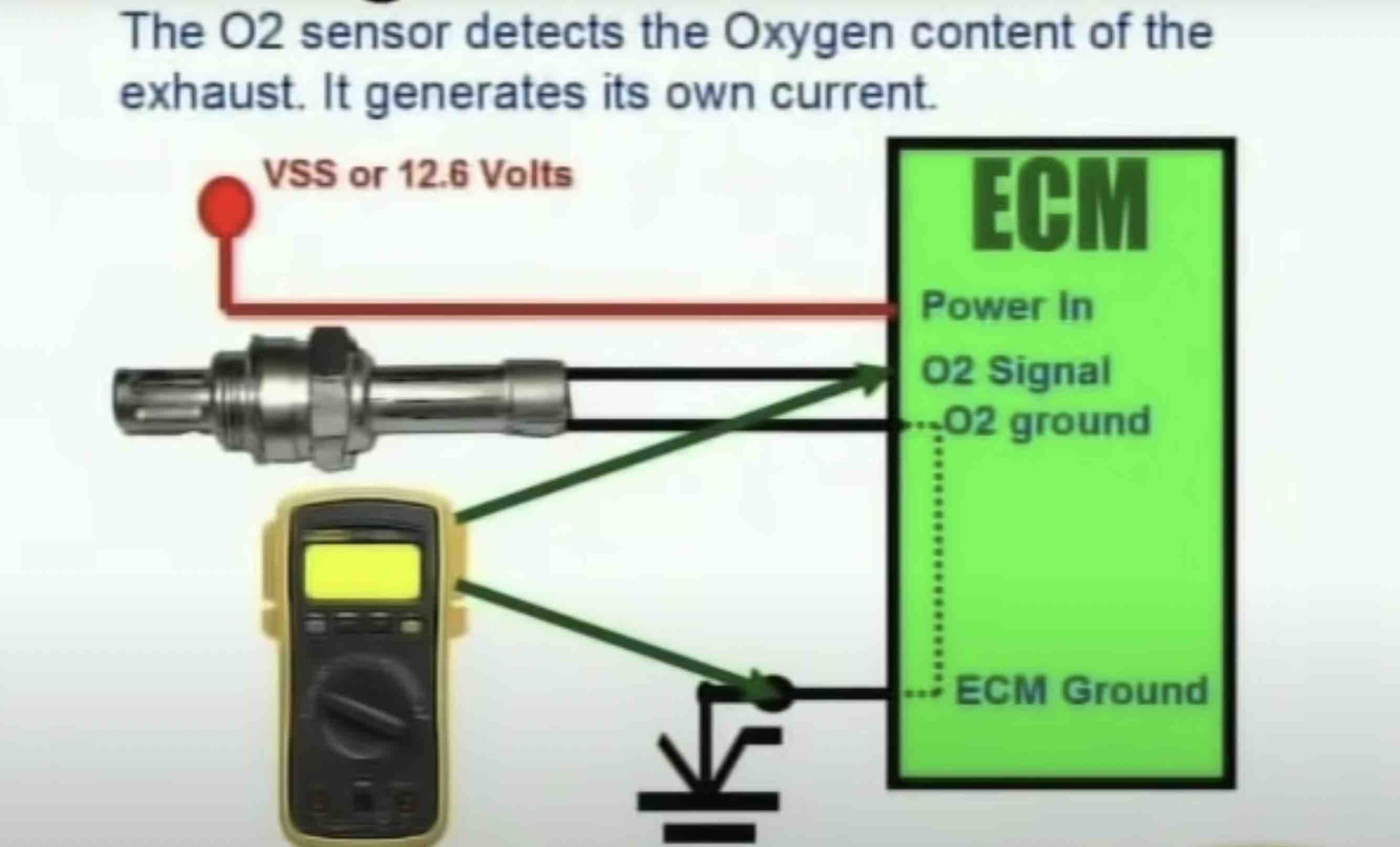
Welcome, fellow gearheads! Today, we're diving deep into the wiring of a 4-wire Oxygen (O2) sensor in a Dodge vehicle. Understanding this system is crucial for diagnosing engine performance issues, performing repairs, or even undertaking modifications. Whether you're troubleshooting a pesky check engine light or prepping for an engine swap, a solid grasp of this wiring diagram will prove invaluable.
Why Bother With This Wiring Diagram?
Having the correct wiring diagram for your 4-wire O2 sensor unlocks a wealth of possibilities:
- Accurate Diagnostics: Mismatched wiring can throw off sensor readings, leading to misdiagnosis and wasted time and money. The diagram ensures you're testing the correct circuits.
- Reliable Repairs: Replacing a faulty O2 sensor is straightforward, but ensuring you reconnect the wires correctly is paramount. A diagram eliminates guesswork.
- Custom Modifications: Swapping engines or modifying the exhaust system often involves adapting the O2 sensor wiring. The diagram provides the foundation for safe and effective modifications.
- General Knowledge: Understanding how this sensor integrates into the engine management system deepens your overall automotive knowledge.
Key Specs and Main Parts of a 4-Wire O2 Sensor
A 4-wire O2 sensor differs from older 1, 2, or 3-wire versions primarily due to its internal heater. Let's break down the essential components:
- Sensor Element (Zirconium Dioxide or Titania): This is the heart of the sensor. It generates a voltage signal based on the difference in oxygen concentration between the exhaust gas and the ambient air. Older sensors typically used Zirconium Dioxide (ZrO2), while newer ones sometimes utilize Titania (TiO2).
- Heater Element: The heater is crucial for bringing the sensor up to its operating temperature (around 600°F or 315°C) quickly. This ensures accurate readings, especially during cold starts when exhaust gases haven't heated the sensor sufficiently. Without the heater, the engine control unit (ECU) would rely on inaccurate readings, negatively impacting fuel economy and emissions.
- Sensor Signal Wire: This wire carries the voltage signal generated by the sensor element to the ECU. The voltage typically varies between 0.1V (lean) and 0.9V (rich).
- Sensor Ground Wire: Provides a reference point for the sensor signal, completing the circuit.
- Heater Power Wire: Supplies power to the heater element, usually a 12V source.
- Heater Ground Wire: Completes the circuit for the heater element.
Why four wires? Simple. Two wires are dedicated to the sensor signal and ground, while the other two power and ground the internal heater. This separation ensures faster and more accurate oxygen readings, resulting in better fuel efficiency and reduced emissions.
Decoding the Wiring Diagram: Symbols and Conventions
Understanding the symbols used in a 4-wire O2 sensor wiring diagram is key to interpreting it correctly. While specific diagrams may vary slightly, here are the common elements:
- Wires: Represented by solid lines. The thickness might indicate the wire gauge (thicker lines = thicker wires).
- Colors: Wire colors are crucial for identification. Common colors for Dodge O2 sensors include:
- Black: Sensor Ground
- Gray: Sensor Signal
- White: Heater Power
- White/Other Color: Heater Ground (can also be Blue)
- Connectors: Shown as rectangular or circular symbols, often with numbered pins. The diagram will indicate which wire connects to which pin.
- Ground Symbols: Represented by various symbols (e.g., three downward-pointing lines), indicating a connection to the vehicle's chassis ground.
- ECU (Engine Control Unit): Often depicted as a rectangle with labeled pins, showing which ECU input the O2 sensor signal connects to.
- Relays and Fuses: The diagram will show any relays or fuses in the heater circuit, indicating their location and amperage rating.
Lines on the diagram represent wires, and their connections at junctions are typically shown with dots. Dashed lines may indicate shielding or signal paths within the ECU.
How It Works: A Deep Dive
The 4-wire O2 sensor's operation relies on the principles of electrochemistry and feedback control. Here's a simplified explanation:
- Heater Activation: When the engine starts (especially when cold), the ECU activates the heater circuit. This rapidly brings the sensor element to its operating temperature.
- Oxygen Sensing: The sensor element (e.g., Zirconium Dioxide) reacts to the oxygen content in the exhaust gas. This reaction generates a voltage signal proportional to the oxygen concentration. A high voltage (around 0.9V) indicates a "rich" mixture (less oxygen), while a low voltage (around 0.1V) indicates a "lean" mixture (more oxygen).
- Signal Transmission: The sensor signal is transmitted to the ECU via the sensor signal wire.
- ECU Interpretation: The ECU analyzes the O2 sensor signal and uses it to adjust the air-fuel mixture. If the signal indicates a rich mixture, the ECU will reduce the amount of fuel injected. Conversely, if the signal indicates a lean mixture, the ECU will increase fuel injection.
- Closed-Loop Control: This process creates a closed-loop feedback system, constantly optimizing the air-fuel mixture for maximum efficiency and minimal emissions.
Real-World Use: Basic Troubleshooting Tips
Here are some practical troubleshooting tips for 4-wire O2 sensor issues:
- Check Engine Light (CEL): O2 sensor problems often trigger the CEL. Use an OBD-II scanner to retrieve the diagnostic trouble codes (DTCs). Common codes include P0135 (O2 Sensor Heater Circuit Malfunction), P0171 (System Too Lean), and P0172 (System Too Rich).
- Visual Inspection: Carefully inspect the wiring harness and connector for damage, corrosion, or loose connections. Pay close attention to the heater circuit wires, as they are prone to heat damage.
- Heater Circuit Testing: Use a multimeter to check for voltage at the heater power wire (with the engine running). Also, check for continuity between the heater ground wire and the vehicle's chassis ground. If the heater isn't getting power or grounded, the sensor won't function correctly.
- Signal Wire Testing: With the engine running and warmed up, use a multimeter to measure the voltage on the sensor signal wire. The voltage should fluctuate between 0.1V and 0.9V as the engine idles. A steady voltage or no voltage indicates a potential sensor issue. You can also use an oscilloscope to visualize the signal waveform.
- Sensor Resistance: You can test the internal resistance of the heater using a multimeter. Consult your vehicle's service manual for the specified resistance range. An open circuit or very high resistance indicates a faulty heater.
Important: Before replacing the O2 sensor, rule out other potential causes, such as vacuum leaks, faulty fuel injectors, or problems with the mass airflow (MAF) sensor.
Safety First!
Working on automotive electrical systems involves inherent risks. Be mindful of the following safety precautions:
- Disconnect the Battery: Always disconnect the negative battery terminal before working on any electrical components. This prevents accidental shorts and potential electrical shocks.
- Hot Exhaust: The exhaust system gets extremely hot. Allow the engine to cool down completely before working on the O2 sensor.
- Fuel System: The fuel system contains pressurized fuel. Be careful when working near fuel lines or injectors.
- Protective Gear: Wear safety glasses and gloves to protect yourself from debris and chemicals.
O2 sensors are exposed to incredibly high temperatures, especially those close to the exhaust manifold. The heater circuits, in particular, are susceptible to shorts, so be extra cautious when inspecting and testing them.
Disclaimer: Automotive repair can be dangerous. This information is for educational purposes only and should not be considered professional advice. Always consult a qualified mechanic before performing any repairs on your vehicle.
We have a detailed 4-wire O2 sensor wiring diagram file specifically tailored for various Dodge models. This diagram includes wire colors, connector pinouts, and component locations. This can be a valuable resource for troubleshooting and repair. You can download it using the provided link.