
4 Wire O2 Sensor Wiring Diagram Honda
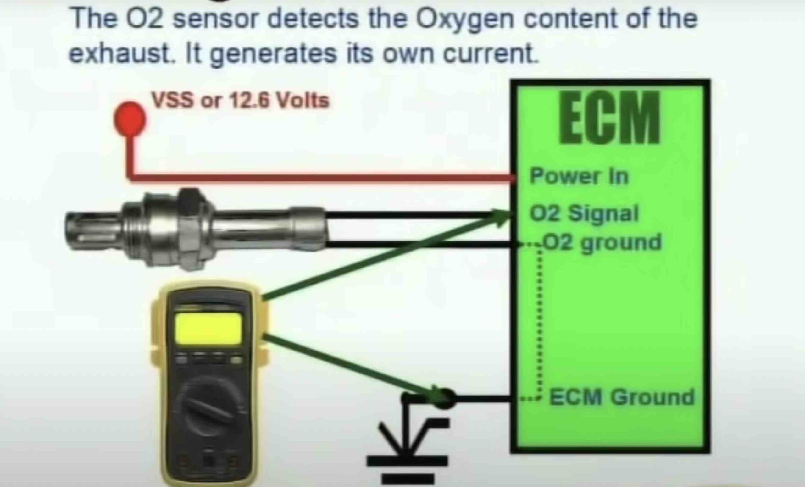
If you're tackling O2 sensor issues on your Honda, understanding the 4-wire O2 sensor wiring diagram is absolutely crucial. Whether you're diagnosing a pesky check engine light, performing a sensor replacement, or even diving into some modifications, this guide will equip you with the knowledge you need. Think of it as your roadmap to the sensor's electrical system.
Why This Diagram Matters
The 4-wire O2 sensor is a common type found in many Honda vehicles, especially those manufactured from the mid-90s onwards. Knowing the wiring configuration allows you to:
- Diagnose faults: Determine if the sensor itself is faulty or if there's a problem in the wiring harness, ECU (Engine Control Unit), or associated circuits.
- Perform repairs: Correctly splice wires after damage, replace connectors, or repair short circuits.
- Install aftermarket components: Properly wire in wideband O2 sensors, data loggers, or other performance enhancing parts.
- Understand engine management: Get a deeper grasp of how the ECU uses O2 sensor data for fuel trim and emissions control.
Without a good understanding, you risk damaging the sensor, the ECU, or even causing a fire. This guide provides that understanding.
Key Specs and Main Parts
A 4-wire O2 sensor has four wires, each serving a specific purpose. The most common functions are:
- Heater Power (12V): Provides voltage to the heater element.
- Heater Ground: Completes the circuit for the heater element.
- Sensor Signal: The analog voltage signal representing the oxygen content in the exhaust gas.
- Sensor Ground: The ground reference for the sensor signal.
It's crucial to identify each wire correctly. Wiring diagrams often use abbreviations like HT (heater), SIG (signal), and GND (ground). The exact wire colors can vary slightly between Honda models and years, so always refer to the specific diagram for your vehicle. The location of the sensor (upstream or downstream of the catalytic converter) also matters, as the wiring can be slightly different.
Key Specs to Consider:
- Voltage Range: The signal wire typically outputs a voltage between 0.1V and 0.9V. 0.1V indicates a lean condition (excess oxygen), and 0.9V indicates a rich condition (insufficient oxygen).
- Heater Resistance: The heater element should have a specific resistance, usually between 5 and 20 ohms. You can measure this with a multimeter.
Understanding the Wiring Diagram Symbols
Wiring diagrams use standardized symbols to represent different components and connections. Here's a breakdown of common symbols you'll encounter in a Honda 4-wire O2 sensor diagram:
- Solid Lines: Represent wires. Thicker lines often indicate a power wire.
- Dashed Lines: Can represent shielding, ground connections, or circuits that are only active under certain conditions.
- Boxes or Rectangles: Represent components like the O2 sensor itself, relays, or fuses. Sometimes they will have internal diagrams depicting how that component works.
- Circles: Often represent connectors or splice points.
- Ground Symbol (Usually three descending horizontal lines): Indicates a connection to the vehicle's chassis ground.
- ECU (Engine Control Unit) Representation: A larger box or rectangle, with pins numbered to indicate which wires connect to specific inputs and outputs.
Color Codes:
Wire colors are often abbreviated. For example:
- BLK: Black
- WHT: White
- RED: Red
- GRN: Green
- BLU: Blue
- YEL: Yellow
Wires can also have stripes, indicated by a slash and the color of the stripe (e.g., BLK/WHT means a black wire with a white stripe).
Connectors: The diagram will show connector numbers and pin assignments. This is critical when troubleshooting because it tells you exactly which wire corresponds to which pin on the connector. Honda connectors often have a locking mechanism; be careful when disconnecting them to avoid damage.
How It Works
The 4-wire O2 sensor is designed to accurately measure oxygen levels in the exhaust stream. Here's a simplified explanation of its operation:
- Heater Element: The heater element quickly brings the sensor up to its operating temperature (around 600°F or 315°C). This is crucial for accurate readings, especially during cold starts. Without the heater, the sensor would take much longer to reach operating temperature, leading to inaccurate fuel trims.
- Oxygen Measurement: The sensor itself contains a ceramic element (usually zirconia or titania) that generates a voltage based on the difference in oxygen concentration between the exhaust gas and the ambient air.
- Signal Generation: A lean mixture (high oxygen content) produces a low voltage (around 0.1V). A rich mixture (low oxygen content) produces a high voltage (around 0.9V).
- ECU Interpretation: The ECU receives this voltage signal and uses it to adjust the air-fuel mixture. If the signal indicates a lean condition, the ECU will increase fuel injection. If the signal indicates a rich condition, the ECU will decrease fuel injection. This process, known as closed-loop fuel control, optimizes fuel efficiency and minimizes emissions.
The sensor's ground provides a stable reference for the voltage signal. Any problems with the ground connection can lead to inaccurate readings and engine performance issues.
Real-World Use - Basic Troubleshooting Tips
Here are some basic troubleshooting tips when working with a 4-wire O2 sensor:
- Check Engine Light (CEL): Use an OBD-II scanner to read the trouble codes. Codes related to the O2 sensor often indicate a faulty sensor, wiring problem, or vacuum leak. Common codes include P0130, P0131, P0132, P0133, P0134, P0135 (and similar codes for other sensors).
- Visual Inspection: Carefully inspect the wiring harness for any damage, such as frayed wires, broken connectors, or corrosion. Pay close attention to the area near the exhaust manifold, where heat can cause damage.
- Multimeter Testing: Use a multimeter to check the following:
- Heater Resistance: Measure the resistance between the two heater wires (usually the two wires of the same color). Compare the reading to the manufacturer's specification. An open circuit indicates a faulty heater.
- Heater Voltage: With the engine running, check for 12V at the heater power wire.
- Signal Voltage: With the engine running and warmed up, monitor the voltage on the signal wire. It should fluctuate between 0.1V and 0.9V. A fixed voltage or no voltage indicates a problem.
- Continuity: Check for continuity between the sensor ground wire and the vehicle's chassis ground. A lack of continuity indicates a ground fault.
- Wiring Diagram Reference: Always refer to the wiring diagram for your specific Honda model and year to ensure you are testing the correct wires.
Troubleshooting Scenario: Let’s say you get a P0135 code (O2 Sensor Heater Circuit Malfunction). Start by checking the heater resistance. If it's out of spec, the sensor itself is likely the problem. If the resistance is good, check for 12V at the heater power wire. If there's no voltage, the problem is in the wiring or the ECU. If there is voltage, but the sensor still isn't heating up (you can sometimes feel it), you likely have a bad sensor that's still conducting, but not heating effectively.
Safety First!
Working with automotive electrical systems can be dangerous. Keep the following safety precautions in mind:
- Disconnect the Battery: Always disconnect the negative battery terminal before working on any electrical components. This prevents accidental short circuits.
- Hot Exhaust: Be extremely careful when working around the exhaust system, especially when the engine is hot. Allow the exhaust to cool completely before touching any components.
- Fuel Lines: Be aware of fuel lines in the area. Avoid creating sparks or using open flames near fuel lines.
- Airbag Systems: Be aware of the location of airbag sensors and modules. Incorrect wiring near airbag systems can cause them to deploy unexpectedly.
- Proper Tools: Use the correct tools for the job. Avoid using damaged or worn-out tools.
- Consult a Professional: If you are not comfortable working on automotive electrical systems, consult a qualified mechanic.
High-Risk Components: The ECU is especially vulnerable to damage from incorrect wiring. Always double-check your connections before powering up the system. Short circuits can fry sensitive components in the ECU, requiring expensive repairs or replacement.
Remember, this guide provides a general overview of 4-wire O2 sensor wiring on Hondas. Always consult the specific wiring diagram for your vehicle to ensure accurate diagnosis and repairs. We have the detailed wiring diagram available for download, ready to help you navigate your O2 sensor challenges!