
4 Wire O2 Sensor Wiring Diagram Nissan
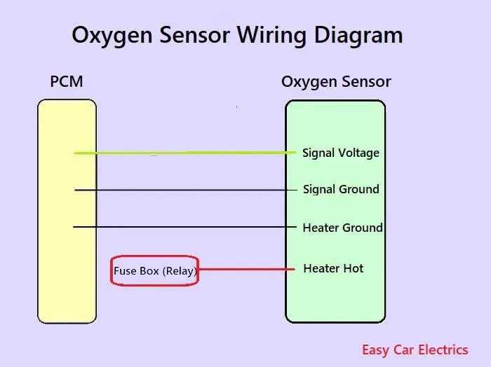
This article delves into the wiring diagram of a 4-wire Oxygen (O2) sensor in a Nissan vehicle. Understanding this diagram is crucial for various tasks, from diagnosing and repairing sensor malfunctions to performing engine modifications or even just expanding your automotive knowledge. We'll break down the components, wiring conventions, and troubleshooting steps, all while keeping the explanations clear and concise.
Purpose of Understanding the 4-Wire O2 Sensor Diagram
Why bother with this diagram? Several reasons:
- Diagnosis and Repair: A faulty O2 sensor can lead to poor fuel economy, rough idling, and even catalytic converter damage. The wiring diagram helps you pinpoint breaks or shorts in the circuit.
- Performance Tuning: Modifying your engine often necessitates understanding how the O2 sensor interacts with the ECU (Engine Control Unit).
- DIY Maintenance: Replacing an O2 sensor is a relatively straightforward DIY project, but understanding the wiring ensures you connect the new sensor correctly.
- General Automotive Knowledge: Comprehending sensor operation and wiring deepens your understanding of how modern engines function.
Key Specs and Main Parts of a 4-Wire O2 Sensor
A 4-wire O2 sensor is a type of sensor that measures the amount of oxygen in the exhaust gases. This information is then sent to the ECU, which uses it to adjust the air-fuel ratio for optimal engine performance and reduced emissions. The "4-wire" designation refers to the number of wires connecting the sensor to the vehicle's electrical system. These wires serve specific purposes:
- Sensor Signal Wire: This wire carries the voltage signal generated by the sensor, representing the oxygen concentration in the exhaust. This is the most important wire for measuring the sensor's output. Typically varies between 0.1V (lean) and 0.9V (rich).
- Sensor Ground Wire: This wire provides a stable ground reference for the sensor signal, ensuring accurate readings.
- Heater Power Wire: The heater element is crucial because O2 sensors only function correctly at high temperatures (around 600°F/315°C). This wire supplies power to the heater.
- Heater Ground Wire: This wire completes the circuit for the heater element.
The heart of the sensor is a zirconia dioxide (ZrO2) or titania (TiO2) element. This element generates a voltage proportional to the difference in oxygen concentration between the exhaust gas and the ambient air outside the sensor. The heater element ensures the sensor reaches its operating temperature quickly, especially during cold starts. Upstream sensors (before the catalytic converter) are typically wideband sensors, which can measure a wider range of air-fuel ratios than downstream sensors (after the catalytic converter).
Understanding the Wiring Diagram Symbols
Wiring diagrams use standardized symbols to represent electrical components and connections. Here's a breakdown of common symbols you'll encounter in a Nissan 4-wire O2 sensor diagram:
- Lines: Solid lines represent wires. Dashed lines may indicate shielded wires or connections internal to a module. Line thickness doesn't typically indicate wire gauge.
- Circles: Circles often represent connectors or splices in the wiring harness.
- Squares/Rectangles: These usually represent components like the ECU or relays. Some are marked with their function.
- Ground Symbol (⏚): This symbol indicates a connection to the vehicle's chassis ground.
- Battery Symbol (+): Indicates the positive terminal of the battery and a source of voltage.
- Resistor Symbol ( ): Could be the sensor's internal resistance or an external resistor in the circuit.
Color Codes: Nissan uses standard color codes for wiring. While these can vary slightly depending on the model year, some common colors for O2 sensor wiring include:
- Black: Often used for sensor ground.
- White: Often used for heater ground.
- Blue or Green: Typically the sensor signal wire.
- Yellow or Red: Typically the heater power wire.
Always refer to the specific wiring diagram for your Nissan model and year, as color codes can vary. Do not assume the color will be the same.
How the 4-Wire O2 Sensor System Works
The O2 sensor plays a critical role in the engine's feedback loop. Here's a simplified explanation of how it works:
- Exhaust Gas Monitoring: The sensor is located in the exhaust stream, constantly exposed to exhaust gases.
- Oxygen Measurement: The sensing element inside the sensor measures the oxygen concentration in the exhaust.
- Signal Generation: Based on the oxygen concentration, the sensor generates a voltage signal. A lean mixture (excess oxygen) produces a low voltage (around 0.1V), while a rich mixture (lack of oxygen) produces a high voltage (around 0.9V).
- Signal Transmission: The voltage signal is transmitted to the ECU via the sensor signal wire.
- ECU Interpretation: The ECU analyzes the O2 sensor signal and compares it to pre-programmed target values.
- Air-Fuel Ratio Adjustment: Based on the O2 sensor feedback, the ECU adjusts the amount of fuel injected into the engine to maintain the optimal air-fuel ratio (typically 14.7:1, known as stoichiometric).
- Heater Activation: The ECU controls the heater circuit to ensure the sensor reaches its operating temperature quickly and maintains it consistently.
Real-World Use: Basic Troubleshooting Tips
Here are some basic troubleshooting steps you can perform using the wiring diagram:
- Visual Inspection: Check the sensor and wiring for any obvious damage, such as broken wires, melted connectors, or corrosion.
- Continuity Testing: Use a multimeter to check for continuity between the sensor wires and their corresponding terminals in the ECU connector. A lack of continuity indicates a broken wire.
- Voltage Testing: With the engine running, use a multimeter to check for the presence of voltage on the heater power wire. No voltage indicates a problem with the heater circuit (fuse, relay, or wiring).
- Signal Voltage Monitoring: Use a multimeter or scan tool to monitor the sensor signal voltage. The voltage should fluctuate between approximately 0.1V and 0.9V. A constant voltage or no voltage indicates a faulty sensor or wiring issue.
- Check for DTC codes: Use an OBDII scan tool to retrieve Diagnostic Trouble Codes (DTCs). Codes related to the O2 sensor can provide valuable clues about the nature of the problem. Common codes include P0130-P0167 (O2 Sensor Circuit Malfunction) and P0171/P0174 (Lean Condition).
Example: If you suspect a broken heater circuit, use the wiring diagram to identify the heater power and ground wires. Use a multimeter to check for voltage at the heater power wire (with the ignition on). If there's no voltage, trace the circuit back to the fuse box and relay, checking for blown fuses or faulty relays.
Safety Precautions
Working on automotive electrical systems can be dangerous. Take the following precautions:
- Disconnect the Battery: Always disconnect the negative battery cable before working on any electrical components.
- Be Careful with Hot Exhaust: Ensure the engine and exhaust system are completely cool before working on the O2 sensor to avoid burns.
- Use Proper Tools: Use insulated tools and a multimeter with appropriate voltage and current ratings.
- Avoid Short Circuits: Be careful not to create short circuits by accidentally touching wires together.
- Fuel Lines: Keep fuel lines and fuel vapors away from any heat source.
The most dangerous component directly related to the O2 sensor is the exhaust system itself. It gets extremely hot and can cause severe burns. Allow sufficient time for the system to cool down before working on the sensor.
We understand that having a visual aid is extremely useful. We have a detailed wiring diagram for the 4-Wire O2 sensor used in many Nissan vehicles. This diagram provides the specific wire colors and connector pinouts for your vehicle.