
4 Wire Starter Solenoid Wiring Diagram
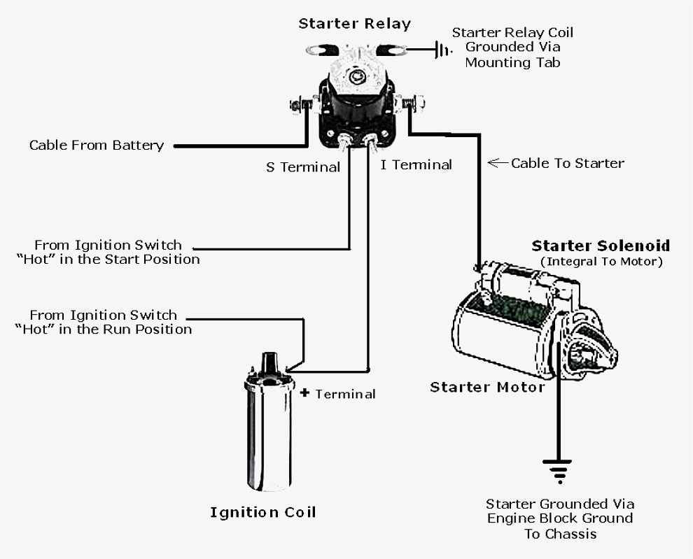
So, you're diving into the world of 4-wire starter solenoids, eh? Excellent choice. Understanding these seemingly simple components is crucial for successful automotive repairs, modifications, and even just general electrical system troubleshooting. This article will walk you through the 4-wire starter solenoid wiring diagram, providing you with the knowledge to diagnose issues, perform safe repairs, and potentially even upgrade your starting system. We'll break down the components, the wiring, and the functionality in a way that's both technically accurate and easily digestible for the experienced DIYer.
Why Understanding This Diagram Matters
Let's be real: staring at a rat's nest of wires without a diagram is a recipe for frustration (and possibly a blown fuse!). The 4-wire starter solenoid wiring diagram provides a crucial roadmap for several scenarios:
- Repair and Diagnostics: When your car won't start, the starter solenoid is a prime suspect. The diagram helps you trace circuits, test voltage drops, and identify faulty components.
- Modifications and Upgrades: Whether you're installing a new high-torque starter or adding a remote start system, understanding the solenoid wiring is essential to prevent electrical damage and ensure proper functionality.
- Learning and Understanding: Simply understanding how the starter system works deepens your automotive knowledge, making you a more confident and capable DIY mechanic.
Key Specs and Main Parts
Before we dive into the wiring, let's identify the key components and their specifications:
The Starter Solenoid
The starter solenoid is essentially an electromagnetic switch. Its primary function is to engage the starter motor and supply it with the large amount of current required to crank the engine. It acts as a high-current relay, allowing a small current from the ignition switch to control a much larger current flow to the starter. Typically, a solenoid’s life expectancy is between 50,000 and 80,000 starts, but can fail earlier due to excessive heat, voltage fluctuations, or physical damage.
The Four Wires (and their connections)
Here's where the "4-wire" part comes in. Each wire plays a distinct role:
- Battery Positive (+12V): This heavy-gauge wire (typically 8 gauge or thicker) provides the main power source for the starter motor. It connects directly to the positive terminal of the battery and then to the solenoid terminal that feeds the starter.
- Starter Motor Connection: Another heavy-gauge wire (similar to the battery cable), this connects the solenoid to the starter motor itself. When the solenoid is energized, it connects this terminal to the battery positive terminal, sending power to the starter.
- Ignition Switch Signal (Start Signal): A smaller-gauge wire (typically 16-18 gauge) that receives a +12V signal from the ignition switch when the key is turned to the "start" position. This signal energizes the solenoid's internal coil. This signal is typically a momentary +12V source that disappears when the key is released.
- Ground: The solenoid *must* have a reliable ground connection to complete the circuit and allow the solenoid to function. This can be a dedicated wire to the chassis ground, or the solenoid may ground through its mounting bracket. A poor ground connection is a common cause of starter problems.
Symbols: Decoding the Wiring Diagram
Understanding the symbols used in the wiring diagram is crucial for proper interpretation:
- Solid Lines: Represent wires. Thicker lines usually indicate higher current-carrying capacity.
- Dashed Lines: Can represent shielded cables or wiring that is internal to a component.
- Color Coding: Standard color coding (e.g., red for power, black for ground) helps identify wires quickly. However, be aware that aftermarket installations may deviate from these standards. Always verify with a multimeter.
- Connectors: Represented by circles or squares where wires connect. They often have numbers or letters indicating pin assignments.
- Ground Symbol: Looks like a downward-pointing tree or a series of horizontal lines getting progressively shorter.
- Battery Symbol: A series of alternating long and short parallel lines, with + and - signs indicating polarity.
- Solenoid Symbol: Typically represented by a coil symbol and a switch, indicating the electromagnetic nature of the device.
How It Works: The Starting Sequence
Here's a simplified breakdown of how the 4-wire starter solenoid functions within the starting system:
- Ignition Key to "Start": When you turn the ignition key to the "start" position, a +12V signal is sent from the ignition switch to the ignition switch signal wire of the solenoid.
- Solenoid Activation: This signal energizes the solenoid's internal coil, creating a strong magnetic field.
- Plunger Movement: The magnetic field pulls a plunger inside the solenoid.
- Contact Closure: The plunger's movement closes heavy-duty contacts inside the solenoid. These contacts connect the battery positive terminal directly to the starter motor connection terminal.
- Starter Motor Engagement: The starter motor receives the high-current flow and engages the engine's flywheel via the starter drive, causing the engine to crank.
- Key Release: When you release the key from the "start" position, the signal from the ignition switch is removed. The magnetic field collapses, the plunger returns to its original position, and the contacts open, disconnecting the battery from the starter motor.
Real-World Use: Basic Troubleshooting
Here are some common issues and how to troubleshoot them using the wiring diagram and a multimeter:
- No Cranking at All:
- Check the battery voltage. It should be at least 12.4V.
- Verify the ignition switch signal wire is receiving +12V when the key is in the "start" position. If not, the problem lies upstream (ignition switch, wiring).
- Check the ground connection to the solenoid. Clean and tighten the ground connection to ensure good contact. Use a multimeter to measure the resistance between the solenoid housing and the chassis ground; it should be very close to zero ohms.
- If the signal wire is good and the ground is good, the solenoid itself may be faulty. You can try "jumping" the solenoid by connecting the battery positive terminal directly to the starter motor connection terminal (with the ignition off and the vehicle in park or neutral!). If the starter cranks, the solenoid is definitely bad.
- Clicking Sound But No Cranking:
- This often indicates a weak battery or a bad connection in the high-current path. Check the battery terminals, starter motor connections, and solenoid connections for corrosion and tightness.
- A worn starter motor can also cause this issue. The motor may be drawing excessive current, causing the solenoid to click but not engage.
- Starter Motor Spins But Doesn't Engage the Flywheel:
- This typically indicates a problem with the starter drive (Bendix drive) inside the starter motor, not the solenoid. The solenoid is likely functioning correctly, but the starter motor isn't properly engaging the engine.
Safety: Handle with Care!
The starter circuit carries extremely high current. Working on it presents several potential hazards:
- Short Circuits: A short circuit can cause sparks, fires, and damage to the electrical system. Always disconnect the battery negative terminal before working on the starter circuit.
- Arc Flash: Accidental contact between the battery positive terminal and ground can create a dangerous arc flash. Wear safety glasses and avoid wearing metallic jewelry.
- Moving Parts: Be extremely cautious when testing the starter motor. Ensure the vehicle is in park or neutral and the parking brake is engaged. Accidental engine starting can cause serious injury.
- Battery Acid: Battery acid is corrosive. Wear gloves and eye protection when working around the battery.
Always double-check your work and refer to the vehicle's service manual for specific wiring diagrams and procedures. When in doubt, consult a qualified mechanic.
We've covered the essentials of the 4-wire starter solenoid wiring diagram. With this knowledge, you're well-equipped to tackle basic troubleshooting and repairs. Remember safety first! Good luck!
We have a printable version of the wiring diagram available for download. Contact us, and we'll gladly provide you with the file.