4 Wire Trailer Lights Wiring Diagram
Alright, let's dive into the world of 4-wire trailer light wiring diagrams. If you're looking to troubleshoot existing trailer lights, rewire a trailer from scratch, or simply understand how your trailer's lighting system integrates with your tow vehicle, this is the guide for you. We'll cover everything from the purpose of the diagram to real-world troubleshooting tips, ensuring you can confidently tackle your trailer lighting projects.
Why a 4-Wire Diagram Matters
Understanding a 4-wire trailer light wiring diagram is crucial for several reasons. First and foremost, it allows for accurate and safe connections between your tow vehicle and the trailer. Improper wiring can lead to a whole host of issues, from dim or non-functional lights to short circuits that could damage your vehicle's electrical system. Beyond just functionality, a correctly wired trailer ensures compliance with legal requirements for road safety. Using a diagram, you can:
- Repair Existing Wiring: Quickly identify and fix broken or corroded wires.
- Rewire a Trailer: Confidently connect all the necessary lights during a trailer rebuild or modification.
- Diagnose Electrical Problems: Isolate issues like flickering lights or blown fuses by systematically checking the wiring.
- Understand System Function: Grasp the underlying principles of trailer lighting, making future modifications easier.
Key Specs and Main Parts
The 4-wire system is the most common setup for smaller trailers, handling essential lighting functions. It's characterized by its simplicity and affordability. Here's a breakdown of the key components:
- Trailer Connector: This is the interface between the tow vehicle and the trailer, typically a 4-way flat connector. Other connector types exist (5, 6, and 7-way), but we're focusing on the 4-way in this article.
- Ground Wire: Provides the return path for the electrical current. Essential for completing the circuit! Usually white.
- Tail Light Wire: Powers the tail lights, which illuminate when the tow vehicle's headlights are on. Usually brown.
- Left Turn/Brake Light Wire: Combines the functions of the left turn signal and brake light. Usually yellow.
- Right Turn/Brake Light Wire: Combines the functions of the right turn signal and brake light. Usually green.
- Trailer Lights: Including tail lights, brake lights, and turn signals. These typically use incandescent or LED bulbs.
- Wiring Harness: A collection of wires bundled together to connect the trailer lights to the connector.
Understanding the Diagram: Symbols, Lines, and Colors
The wiring diagram is essentially a roadmap of the electrical system. It uses standardized symbols and colors to represent different components and connections. Here's what you need to know:
- Lines: Represent the wires. Thicker lines might indicate a larger wire gauge (more on that later).
- Colors: Each color corresponds to a specific function, as mentioned above (white for ground, brown for tail lights, etc.). This color-coding is critical for proper wiring.
- Ground Symbol: A series of horizontal lines, usually decreasing in size, indicating the ground connection. Ensure this connection is clean and secure for proper operation.
- Connector Symbol: Typically a rectangle with pins representing the individual connections in the trailer connector.
- Light Bulb Symbol: Represents the trailer lights (tail lights, brake lights, turn signals).
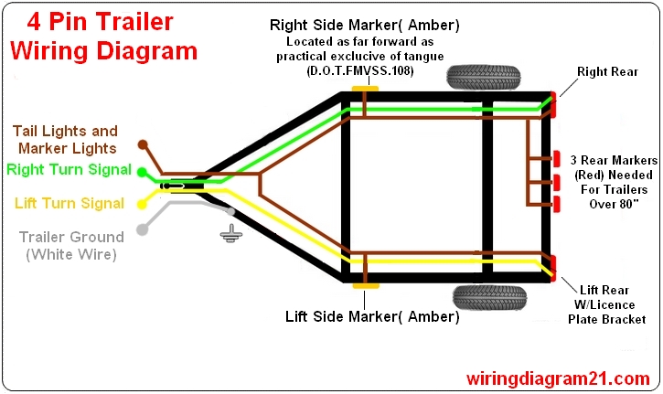
A typical 4-wire trailer light wiring diagram will show the 4-way connector with each pin labeled with its corresponding color and function. The diagram will then trace each wire from the connector to the appropriate trailer light. It will clearly show the ground wire connecting to the trailer frame.
How It Works: The Electrical Circuit
The 4-wire system is a relatively simple parallel circuit. When the tow vehicle's lights are activated, power flows through the corresponding wires to the trailer lights. Let's break down each function:
- Tail Lights: When the tow vehicle's headlights are turned on, power flows through the brown wire to the trailer's tail lights, providing visibility at night.
- Brake Lights: When the brake pedal is pressed, power is sent through both the yellow and green wires simultaneously to illuminate the brake lights on the respective sides of the trailer.
- Turn Signals: When the turn signal is activated, power is sent intermittently through either the yellow (left turn) or green (right turn) wire, causing the corresponding lights to flash.
- Ground: The white wire provides a return path for the current back to the tow vehicle's battery, completing the circuit. Without a proper ground, none of the lights will function correctly. A bad ground is the most common cause of trailer light problems!
It's important to note that in this system, the brake and turn signals share the same wire. This simplifies the wiring but means you cannot have a separate brake light and turn signal light on each side of the trailer.
Real-World Use: Troubleshooting Tips
Trailer light problems can be frustrating, but with a systematic approach and your wiring diagram, you can diagnose and fix most issues. Here are some common problems and how to troubleshoot them:
- No Lights at All: Check the ground connection first! Ensure it's clean, tight, and free of corrosion. Then, check the tow vehicle's trailer light fuse. Use a multimeter to test for voltage at the trailer connector.
- Dim Lights: Could be a bad ground, corroded connections, or undersized wiring (gauge). Check all connections for corrosion and clean them thoroughly. Consider upgrading to a larger wire gauge.
- Flickering Lights: Loose connections are the most likely culprit. Inspect all connections and ensure they are secure. Wire connectors can often come loose and cause intermittent connection.
- One Light Not Working: Check the bulb first. If the bulb is good, use a multimeter to test for voltage at the light socket. Trace the wire back to the connector, looking for breaks or corrosion.
- Brake Lights and Turn Signals Reversed: This indicates incorrect wiring at the connector. Double-check your connections against the wiring diagram.
When troubleshooting, use a multimeter to check for voltage and continuity. A multimeter is an invaluable tool for diagnosing electrical problems. Continuity tests whether a circuit is complete and unbroken, while voltage confirms that power is reaching a specific point.
Safety: Risky Components and Best Practices
Working with electrical systems always carries some risk. Here are some safety precautions to keep in mind:
- Disconnect the Battery: Before working on any wiring, disconnect the negative terminal of the tow vehicle's battery. This prevents accidental short circuits.
- Use Proper Tools: Use insulated tools designed for electrical work.
- Wear Safety Glasses: Protect your eyes from sparks or debris.
- Check Wire Gauge: Ensure the wire gauge is appropriate for the current draw of the lights. Using undersized wire can lead to overheating and fire hazards. A good rule of thumb is to consult a wire gauge chart based on the length of the wire and the amperage it will carry.
- Use Heat Shrink Tubing: After making connections, use heat shrink tubing to insulate the connections and protect them from moisture and corrosion.
- Proper Grounding: As mentioned before, grounding is critical. Make sure the ground connection is clean, tight, and securely connected to the trailer frame.
Disclaimer: Always consult with a qualified electrician if you are unsure about any aspect of trailer wiring. Incorrect wiring can lead to serious safety hazards.
We have a downloadable 4-wire trailer light wiring diagram available. This will be a great visual aid as you work on your trailer. Now that you understand the intricacies of the diagram, you are better equipped to tackle your next trailer wiring project!