
4 Wire Voltage Regulator Wiring Diagram
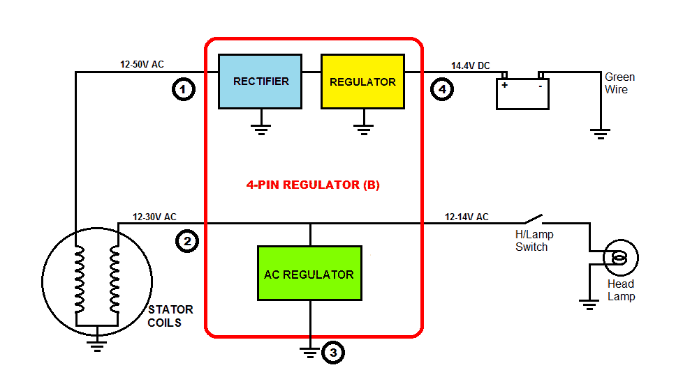
So, you're tackling a voltage regulator issue on your car, huh? Good on you! Understanding the 4-wire voltage regulator wiring diagram is crucial whether you're diagnosing a charging problem, swapping components during a resto-mod, or just expanding your automotive electrical knowledge. This article dives deep into the specifics, giving you the tools to read and understand these vital diagrams. We'll break down the symbols, explain the operation, offer practical troubleshooting advice, and, most importantly, help you stay safe while working with your vehicle's electrical system.
Why Bother with the Diagram?
Let's face it: modern vehicles are incredibly complex. Just randomly poking around with a multimeter can lead to more problems than you solve. A clear, accurate wiring diagram acts as your roadmap. It allows you to:
- Accurately diagnose charging system faults (overcharging, undercharging, no charge).
- Verify wiring during upgrades or modifications (e.g., swapping in a different alternator).
- Repair damaged wiring caused by corrosion, rodent damage, or accidents.
- Understand the system's overall operation and how different components interact.
- Avoid costly mistakes that could damage expensive parts.
Key Specs and Main Parts
The 4-wire voltage regulator is commonly found in older vehicles and some modern applications. Before diving into the diagram, let's define some key parts and specs:
- Voltage Regulator: The heart of the system. Its primary function is to maintain a stable output voltage (typically around 13.8-14.4 volts) to charge the battery and power the vehicle's electrical accessories, regardless of variations in engine speed or load.
- Alternator: The voltage regulator works in conjunction with the alternator. The alternator generates AC voltage, which is rectified (converted to DC) by diodes within the alternator.
- Battery: The energy storage device that provides power when the engine is not running and assists the alternator during high-load situations.
- Wiring Harness: The network of wires connecting all the components.
- 4 Wires: These wires connect the voltage regulator to the alternator, battery, and ignition switch. Each wire has a specific function:
- S (Sense): Monitors the battery voltage. This wire is often connected directly to the battery or a point close to it to provide an accurate voltage reading.
- I (Ignition): Provides power to the voltage regulator when the ignition switch is in the "run" position. This activates the regulator.
- F (Field): Controls the field current supplied to the alternator's rotor. The regulator adjusts this current to control the alternator's output voltage.
- G (Ground): Provides a ground connection for the voltage regulator. A good ground is essential for proper operation.
Diagram Symbols: The Language of Electrical Systems
Wiring diagrams use a standardized set of symbols. Understanding these symbols is key to deciphering the diagram. Here are some common symbols you'll encounter:
- Straight Lines: Represent wires. Thicker lines may indicate heavier gauge wires.
- Dotted Lines: Often indicate optional wiring or wires that are shielded.
- Color Codes: Wires are often color-coded (e.g., red, black, blue, green). The diagram will typically include a legend identifying the color codes and their corresponding circuits.
- Battery Symbol: A series of short and long parallel lines, indicating a DC voltage source.
- Alternator Symbol: Typically a circle with a "Y" inside, representing the stator windings. Sometimes, diodes are also represented inside this symbol.
- Voltage Regulator Symbol: A rectangle or square with terminals labeled S, I, F, and G.
- Ground Symbol: A series of horizontal lines decreasing in length, indicating a connection to the chassis ground.
- Fuse Symbol: A zigzag line inside a rectangle or a straight line with rounded ends, representing a circuit protection device.
- Switch Symbol: A break in a line that can be opened or closed to control the flow of electricity.
Important Note: Diagrams can vary slightly depending on the manufacturer and vehicle model. Always refer to the specific wiring diagram for your vehicle. We've got a generic one available for download at the end of this article, but always cross-reference it.
How It Works: A Simplified Explanation
The 4-wire voltage regulator system works on a feedback loop. Here's a breakdown:
- Ignition Activation: When you turn the key to the "run" position, the ignition wire (I) supplies power to the voltage regulator.
- Voltage Sensing: The regulator monitors the battery voltage through the sense wire (S).
- Field Current Control: Based on the battery voltage, the regulator adjusts the amount of current flowing through the field wire (F) to the alternator's rotor.
- Alternator Output: The field current determines the strength of the alternator's magnetic field. A stronger magnetic field results in a higher output voltage.
- Voltage Regulation: The regulator continuously adjusts the field current to maintain a stable output voltage, ensuring the battery is properly charged and the vehicle's electrical system is protected from overvoltage.
- Grounding: The ground wire (G) provides a stable reference point for the regulator's internal circuitry. A poor ground connection can lead to erratic voltage regulation.
Real-World Use: Basic Troubleshooting
Here are some common problems you might encounter and how the wiring diagram can help:
- Battery Not Charging: Use the diagram to check the continuity of all four wires. Make sure the S wire has a good connection to the battery, the I wire is receiving power when the ignition is on, the F wire is properly connected to the alternator, and the G wire has a solid ground connection. Use a multimeter to test for voltage drops along each wire.
- Overcharging: This is often caused by a faulty voltage regulator. However, use the diagram to verify the wiring first. A short circuit in the S wire can trick the regulator into thinking the battery voltage is low, causing it to overcharge.
- Erratic Voltage Readings: This can be caused by a loose or corroded connection in any of the four wires. Inspect the connectors for corrosion and ensure they are properly seated. Pay special attention to the ground connection.
Safety First: Dealing with Automotive Electrical Systems
Working with automotive electrical systems can be dangerous. Here are some essential safety precautions:
- Disconnect the Battery: Always disconnect the negative battery terminal before working on any electrical components. This will prevent accidental short circuits and potential shocks.
- Use Proper Tools: Use insulated tools designed for automotive electrical work.
- Avoid Working in Wet Conditions: Water can conduct electricity, increasing the risk of electric shock.
- Be Careful Around the Alternator: The alternator can generate high voltages and currents. Avoid touching the terminals while the engine is running. The large capacitor inside can hold a charge even after the car is turned off.
- Double-Check Your Work: Before reconnecting the battery, carefully double-check all your connections to ensure they are correct and secure.
Warning: The battery and alternator contain sulfuric acid and can explode if short-circuited. Exercise extreme caution.
Understanding the 4-wire voltage regulator wiring diagram is a significant step toward confidently tackling automotive electrical repairs. Armed with this knowledge, a multimeter, and a dose of caution, you'll be well-equipped to diagnose and resolve charging system problems. Remember to always consult the specific wiring diagram for your vehicle and follow proper safety procedures.
We have a downloadable version of a generic 4-wire voltage regulator wiring diagram available. It's a great reference tool to keep handy.