4.0 V6 Ford Explorer 4.0 Firing Order Diagram
Understanding the firing order of your 4.0L V6 Ford Explorer is crucial for a variety of tasks, from basic tune-ups to more complex engine diagnostics and repairs. This article delves into the specifics of the firing order diagram for this engine, providing you with the knowledge and understanding needed to confidently tackle related automotive projects. We'll cover everything from the diagram's purpose and key components to real-world troubleshooting and safety considerations.
Purpose of the Firing Order Diagram
The firing order diagram is essentially a roadmap for the combustion process within your engine. It shows the sequence in which each cylinder ignites its air-fuel mixture. Knowing this sequence is essential for several reasons:
- Proper Ignition Timing: Ensures the spark plugs fire at the correct moment for optimal combustion.
- Accurate Diagnosis: Helps pinpoint misfires or other engine performance issues by identifying which cylinder(s) are malfunctioning.
- Routine Maintenance: Necessary for tasks like spark plug replacement, distributor cap and rotor installation (on older systems), and ignition coil testing.
- Engine Swaps/Rebuilds: Absolutely vital when reassembling an engine to ensure proper connection of spark plug wires to the distributor or coil packs.
Without the correct firing order, your engine will run poorly, if at all. Misfires, rough idling, and a significant loss of power are common symptoms of an incorrect firing order. In severe cases, it can even damage the engine.
Key Specs and Main Parts of the 4.0L V6
Before diving into the diagram, let's cover some key specifications of the 4.0L V6 found in various Ford Explorers (primarily from the early 1990s through the 2010s). Note that specific details may vary slightly depending on the year and model.
- Engine Configuration: 4.0L (245 cu in) V6, overhead valve (OHV) or single overhead cam (SOHC) depending on the year.
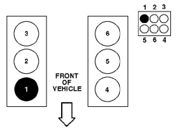
- Firing Order: 1-4-2-5-3-6
- Cylinder Numbering: The passenger side of the engine (bank 1) is numbered 1-2-3 from front to back. The driver's side (bank 2) is numbered 4-5-6 from front to back.
- Ignition System: Typically a distributorless ignition system (DIS) with coil packs, especially in newer models. Older models may use a traditional distributor.
Main Parts involved in the ignition system, which are relevant to the firing order diagram, include:
- Spark Plugs: Ignite the air-fuel mixture in each cylinder.
- Spark Plug Wires: Transmit the high-voltage spark from the ignition coils to the spark plugs (not present in all DIS systems).
- Ignition Coils: Generate the high-voltage spark needed for ignition. DIS systems have multiple coils, often one per cylinder or one coil for a pair of cylinders.
- Crankshaft Position Sensor (CKP): Provides information to the engine control unit (ECU) about the crankshaft's position, allowing the ECU to determine when to fire each cylinder.
- Camshaft Position Sensor (CMP): (On SOHC engines) Provides information to the ECU about the camshaft's position.
- Engine Control Unit (ECU): Controls the ignition timing and other engine functions.
Understanding the Firing Order Diagram
The firing order diagram visually represents the sequence in which the cylinders of your 4.0L V6 engine fire. The diagram typically shows the engine block, cylinder numbers, and the order in which the ignition system sends a spark to each cylinder. Since most 4.0L Explorers use a DIS system, the diagram will emphasize the coil pack layout and connections.
Symbols and Conventions
While specific diagrams might vary, here are some common conventions you'll encounter:
- Cylinder Numbers: Numerically labeled cylinders (1-6) indicating their physical location on the engine block.
- Firing Order Sequence: Usually indicated by a numbered sequence (1, 4, 2, 5, 3, 6) next to each cylinder or coil pack connection, illustrating the order of ignition.
- Lines: Lines connect the ignition coils to the corresponding spark plugs. The length and routing of these lines often represent the actual physical layout under the hood.
- Colors: Some diagrams use color-coding to distinguish between different circuits or coil pack connections. For example, one color might represent the connection for cylinders 1 and 4, another for cylinders 2 and 5, and so on. Consult the diagram's legend for specific color meanings.
- Coil Pack Representation: Diagrams often show a simplified representation of the coil pack(s), indicating the terminals and their corresponding cylinder connections.
How It Works: The Ignition Process
The 4.0L V6 engine's ignition system is controlled by the ECU. The ECU receives signals from the crankshaft position sensor (CKP) and, on SOHC engines, the camshaft position sensor (CMP). These sensors provide the ECU with precise information about the engine's rotational position. Using this information, the ECU determines the optimal timing for each spark plug to fire.
In a DIS system (without a distributor), the ECU sends a signal to the appropriate ignition coil. The coil then generates a high-voltage spark, which is sent through the spark plug wire (if applicable) to the designated spark plug. The spark ignites the air-fuel mixture in the cylinder, initiating the combustion process that drives the piston and ultimately powers the vehicle.
The firing order (1-4-2-5-3-6) dictates the sequence in which the ECU triggers these coils. This sequence ensures a smooth and balanced engine operation, preventing excessive vibrations and maximizing power output.
Real-World Use: Basic Troubleshooting Tips
Here are some troubleshooting scenarios where a firing order diagram proves invaluable:
- Misfires: If your engine is misfiring, use a scan tool to identify the specific cylinder(s) affected. Consult the firing order diagram to ensure the spark plug wires (if applicable) are connected correctly to the coil pack. Swap the coil pack with another cylinder to see if the misfire follows the coil. This will help you determine if the coil itself is faulty.
- Rough Idle: A rough idle can often be caused by incorrect spark plug wire routing. Double-check the diagram to ensure the wires are connected to the correct cylinders.
- Poor Performance: If your vehicle is experiencing a lack of power or poor fuel economy, verify that the spark plugs are in good condition and properly gapped. Also, ensure the ignition coils are functioning correctly by testing their resistance.
Example: Let's say your scan tool indicates a misfire on cylinder #4. Refer to the firing order diagram. Check the spark plug, spark plug wire (if applicable), and ignition coil associated with cylinder #4. Test the coil's resistance and inspect the wire for damage. If the wire and coil seem fine, move to the next step.
Safety Considerations
Working with the ignition system involves high voltage, so always exercise extreme caution.
- Disconnect the Battery: Before working on any part of the ignition system, disconnect the negative battery cable to prevent accidental shocks.
- High Voltage: Ignition coils can generate tens of thousands of volts. Avoid touching any part of the ignition system while the engine is running.
- Fuel: Be mindful of fuel vapors. Work in a well-ventilated area and avoid open flames or sparks.
- Proper Tools: Use insulated tools specifically designed for automotive electrical work.
Never probe or disconnect spark plug wires while the engine is running. This can result in a severe electrical shock.
Remember that diagnosing and repairing engine problems can be complex. If you're unsure about any aspect of the repair, consult a qualified mechanic.
We have a high-resolution firing order diagram specifically for the 4.0L V6 Ford Explorer readily available. It includes clear markings and annotations to help you easily identify the correct connections. Feel free to download it now to assist you with your maintenance and repair tasks.