42 Inch Troy Bilt Bronco Drive Belt Diagram
So, you're tackling a drive belt replacement or just trying to understand the inner workings of your 42-inch Troy-Bilt Bronco? Excellent! Understanding the drive belt system is crucial for maintaining your mower and ensuring it runs smoothly for years to come. This article will walk you through a detailed drive belt diagram, breaking down the components, function, and troubleshooting tips you need to know. We're assuming you're comfortable wrenching on machinery and have some basic mechanical knowledge.
Why This Diagram Matters
A drive belt diagram is far more than just a pretty picture. It's your roadmap for several critical tasks:
- Repairs: Obviously, the diagram is indispensable when replacing a worn or broken drive belt. It shows you the exact routing path, tensioner locations, and pulley alignments. Trying to wing it without a diagram is a recipe for disaster, potential damage, and a belt that slips or breaks prematurely.
- Maintenance: Understanding the belt's path allows you to inspect it regularly for wear, cracks, or fraying. Early detection prevents unexpected breakdowns.
- Troubleshooting: When your mower isn't moving as it should, the diagram helps you pinpoint potential issues like a misaligned pulley, a seized idler arm, or a stretched belt.
- Learning: For those of you interested in how things work, studying the diagram offers a deeper understanding of the mechanical power transmission system in your mower.
Key Specs and Main Parts
Let's dive into the specifics of a typical 42-inch Troy-Bilt Bronco drive belt system. Keep in mind that minor variations may exist between models, but the fundamental principles remain the same.
Main Components:
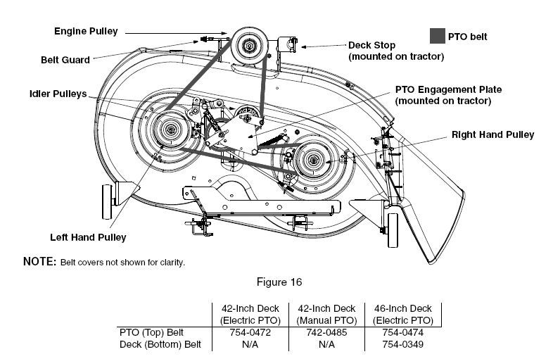
- Engine Pulley: This is the driving force. Connected directly to the engine's crankshaft, it's where the power originates.
- Transmission Pulley: This is the driven component. The belt transfers rotational force from the engine pulley to this pulley, which in turn drives the mower's transmission, propelling the machine forward.
- Drive Belt: The crucial link between the engine and transmission pulleys. It's usually a reinforced rubber belt designed to withstand high tension and friction. The V-shape of the belt is critical for gripping the pulleys properly.
- Idler Pulley(s) / Tensioner Arm: These pulleys, often spring-loaded, maintain proper belt tension. The tensioner arm applies pressure to the belt, preventing slippage and ensuring efficient power transfer. They can be a single pulley or multiple, depending on the mower design.
- Belt Guides: These are small metal arms or brackets positioned near the pulleys. They help prevent the belt from jumping off the pulleys, especially during sudden changes in speed or direction.
Key Specifications:
While specific belt lengths vary, a typical 42-inch Troy-Bilt Bronco will use a drive belt in the range of 80-90 inches in outside circumference. However, never rely solely on a measurement. Always cross-reference with your mower's model number and the manufacturer's recommended belt part number. Using the wrong belt can lead to poor performance and premature failure.
Belt width is also important. A standard A-section V-belt (approximately 1/2 inch wide at the top) is common, but again, verify the correct specification for your model.
Understanding Diagram Symbols
A good drive belt diagram employs standardized symbols to represent different components and their relationships. Here's a breakdown of common symbols:
- Solid Lines: Typically represent the drive belt itself. The thickness of the line might indicate the belt's position (e.g., thicker line for the visible section, thinner for the hidden section).
- Dashed Lines: Usually indicate parts of the belt that are located behind other components or are otherwise obscured from direct view.
- Circles: Represent pulleys. Smaller circles are typically idler pulleys, while larger circles represent the engine and transmission pulleys.
- Arrows: Indicate the direction of belt travel. Pay close attention to these; incorrect routing will prevent the mower from moving.
- Spring Symbols: Illustrate the spring-loaded tensioner arm. They show the direction of force applied by the spring, which maintains belt tension.
- Mounting Points: Small triangles or circles attached to components indicate mounting points to the mower's frame.
Colors are less standardized but can be helpful. Some diagrams use different colors to distinguish between the drive belt and other components or to highlight specific areas of interest.
Some diagrams might use icons to represent specific parts. For instance, a small engine icon near the engine pulley, or a transmission icon near the transmission pulley.
How It Works: The Mechanics of Motion
The drive belt system is a relatively simple yet effective mechanism for transmitting power from the engine to the wheels. Here's a simplified explanation:
- The engine's crankshaft rotates, turning the engine pulley.
- The drive belt, wrapped around the engine pulley, is forced to rotate along with it.
- The belt's rotation transmits power to the transmission pulley.
- The transmission pulley's rotation engages the transmission, which drives the wheels, propelling the mower forward.
- The idler pulley and tensioner arm maintain constant tension on the belt, preventing slippage and ensuring efficient power transfer. Without proper tension, the belt would slip, resulting in reduced speed and potential damage to the belt and pulleys.
The V-shape of the belt is crucial. As tension is applied, the belt wedges itself into the grooves of the pulleys, creating a high-friction contact surface that minimizes slippage. This wedging action amplifies the force transmitted by the belt.
Real-World Use: Basic Troubleshooting
Here are some common issues and how the drive belt diagram can help you diagnose them:
- Mower Doesn't Move: Check the belt. Is it broken? Is it off the pulleys? Use the diagram to ensure the belt is properly routed. A slipping belt can also cause this. Ensure the tensioner arm is functioning correctly.
- Mower Moves Slowly: The belt may be worn and slipping. Inspect it for wear, cracks, or glazing. Also, check the tensioner arm. A weak spring can lead to insufficient belt tension.
- Belt Keeps Coming Off: Misaligned pulleys or damaged belt guides are prime suspects. Use the diagram to verify that all pulleys are in the correct position and alignment. Ensure the belt guides are in place and not bent.
- Squealing Noise: Often indicates a slipping belt. Check belt tension. A worn belt or glazed pulleys can also cause squealing.
Important: Before performing any maintenance or troubleshooting, disconnect the spark plug wire to prevent accidental starting.
Safety First: Risky Components
Working on the drive belt system involves several potential hazards:
- Moving Parts: Never work on the mower while the engine is running. Even with the mower disengaged, the engine pulley is rotating.
- Spring Tension: The tensioner arm is spring-loaded. Be careful when removing or installing it. Use appropriate tools to relieve the spring tension gradually. Never release the spring suddenly, as it can cause serious injury.
- Sharp Edges: Pulleys and belt guides can have sharp edges. Wear gloves to protect your hands.
- Heat: The engine and surrounding components can be hot. Allow the engine to cool down before working on the drive belt system.
Always wear safety glasses to protect your eyes from debris. If you're unsure about any procedure, consult a qualified mechanic.
By understanding the drive belt diagram and the principles behind the system, you can confidently maintain and repair your 42-inch Troy-Bilt Bronco, saving money and extending the life of your machine. Remember to always prioritize safety and consult the manufacturer's service manual for specific instructions and torque specifications.
We have a high-resolution PDF file of the 42-inch Troy-Bilt Bronco drive belt diagram available for download. [Link to Download Here - Replace with actual link] This will give you a clear, detailed view of the system, making your repairs and maintenance tasks much easier.