
4.3 Vortec Crank Sensor Wiring Diagram
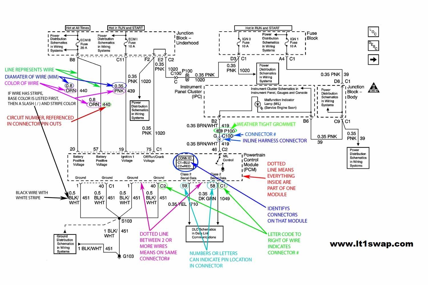
Let's dive into the 4.3 Vortec crank sensor wiring diagram. This isn't just a piece of paper; it's the roadmap to understanding a critical part of your engine's operation. Whether you're troubleshooting a no-start condition, swapping an engine, or simply trying to better understand your 4.3 Vortec, knowing this wiring diagram inside and out is invaluable.
Purpose and Importance
The crank position sensor (CKP sensor) is absolutely vital for your 4.3 Vortec's operation. It tells the Engine Control Unit (ECU), also known as the Powertrain Control Module (PCM) in many GM applications, the exact position and rotational speed of the crankshaft. This information is essential for proper ignition timing and fuel injection. A faulty crank sensor, or a wiring problem associated with it, can lead to a range of issues, from poor performance and stalling to a complete no-start condition. Understanding the wiring diagram allows you to accurately test the sensor, trace faults, and repair wiring issues, saving you time and money.
Key Specs and Main Parts of the Circuit
Before we look at the diagram itself, let's define the key components:
- Crankshaft Position (CKP) Sensor: This sensor is typically a magnetic pickup sensor (sometimes called a variable reluctance sensor) or a Hall-effect sensor. It generates a signal based on the movement of the crankshaft's reluctor ring (a toothed wheel).
- PCM/ECU: The brain of the operation. It receives the signal from the CKP sensor and uses it to control ignition and fuel injection.
- Wiring Harness: The network of wires that connects the CKP sensor to the PCM. This is where most problems occur.
- Connectors: These provide the physical connections between the sensor, wiring harness, and PCM. Corrosion and loose connections here are common culprits.
Typical 4.3 Vortec CKP sensors have three wires:
- Power (usually 5V Reference): Supplied by the PCM to power the sensor (not always present in variable reluctance sensors).
- Ground: Provides a return path for the sensor's electrical circuit.
- Signal: The wire that carries the CKP sensor's signal back to the PCM.
Understanding the Symbols in the Wiring Diagram
Wiring diagrams can seem daunting at first, but once you understand the symbols, they become much clearer. Here's a breakdown of common symbols you'll find in a 4.3 Vortec CKP sensor wiring diagram:
- Solid Lines: Represent wires. The thickness of the line usually doesn't signify anything other than visual clarity.
- Dashed Lines: May indicate a shielded wire or a wire that is part of a larger harness and its specific routing.
- Circles/Dots: Connection points where wires are joined together.
- Rectangles: Represent components like the PCM or the CKP sensor itself (often labeled).
- Ground Symbol (Usually three horizontal lines, getting smaller as they go down): Indicates a connection to the vehicle's chassis ground.
- Connectors: Usually depicted as a stylized plug and socket arrangement. Connector numbers are often included for identification.
- Color Codes: Wires are usually identified by color codes (e.g., RED, BLK, WHT/BLU). These codes are essential for tracing wires.
- Numbers: Indicate pin numbers on connectors or component terminals.
Color coding is especially important. Common colors you'll see include:
- RED: Typically used for power (often fused).
- BLK (Black): Typically used for ground.
- WHT (White): Can be used for signals or other general-purpose wires.
- Other Colors (e.g., BLU, GRN, YEL): Used for specific signals or functions. Always refer to the diagram for their exact purpose.
How It Works: The CKP Sensor Circuit in Action
The 4.3 Vortec's CKP sensor circuit operates as follows:
- The PCM provides a 5V reference voltage (in some sensor types) to the CKP sensor.
- As the crankshaft rotates, the reluctor ring passes by the CKP sensor. This movement generates a signal – either a changing magnetic field (in variable reluctance sensors) or a switching voltage (in Hall-effect sensors).
- The CKP sensor sends this signal back to the PCM via the signal wire.
- The PCM interprets this signal to determine the crankshaft's position and speed.
- Based on this information, the PCM triggers the ignition coil to fire the spark plugs and controls the fuel injectors to deliver the correct amount of fuel.
If the signal is missing, weak, or erratic, the PCM won't be able to accurately control ignition and fuel injection, leading to engine problems.
Real-World Use: Basic Troubleshooting Tips
Here are some troubleshooting tips using the wiring diagram:
- No-Start Condition: If your engine won't start, check the CKP sensor signal using an oscilloscope or a multimeter (set to AC voltage for variable reluctance sensors, or DC voltage for Hall-effect). A missing or abnormal signal could indicate a faulty sensor, wiring problem, or PCM issue.
- Stalling or Rough Running: Intermittent CKP sensor signals can cause stalling or rough running. Check the wiring harness for loose connections, damaged insulation, or corrosion. Pay close attention to the connector at the sensor and the PCM.
- Check Engine Light (CEL): A CKP sensor fault will often trigger a CEL. Use an OBD-II scanner to read the diagnostic trouble code (DTC). Common codes include P0335 (Crankshaft Position Sensor A Circuit), P0336 (Crankshaft Position Sensor A Circuit Range/Performance), and P0337 (Crankshaft Position Sensor A Circuit Low Input).
- Wiring Inspection: Visually inspect the wiring harness for any signs of damage, such as cuts, abrasions, or melted insulation. Use a multimeter to check for continuity and shorts to ground in the wiring.
- Sensor Testing: Use a multimeter to check the sensor's resistance (consult your vehicle's service manual for the correct values). You can also use an oscilloscope to observe the sensor's output signal while cranking the engine.
Example Troubleshooting Scenario: You have a P0335 code and a no-start condition. Using the wiring diagram, you can identify the power, ground, and signal wires. First, check for 5V at the power wire (if applicable) with the ignition on. Then, check for a good ground connection. If both are good, use an oscilloscope to check the signal wire while cranking. If there's no signal, the sensor is likely faulty. If there is a signal, but it's weak or erratic, the wiring or the reluctor ring might be the issue.
Safety Considerations
Working on electrical systems can be dangerous. Keep these points in mind:
- Disconnect the Battery: Always disconnect the negative battery cable before working on any electrical components. This prevents accidental shorts and electrical shocks.
- Handle Connectors Carefully: Avoid pulling on wires when disconnecting connectors. Use a small screwdriver or pick to release the locking tabs.
- Be Aware of High-Voltage Components: The ignition system components, such as the ignition coil, can carry high voltage. Avoid touching these components while the engine is running or the ignition is on.
- Proper Grounding: When testing electrical circuits, ensure that your multimeter or oscilloscope is properly grounded.
- Consult a Professional: If you're not comfortable working on electrical systems, consult a qualified mechanic.
Working near the crankshaft pulley also has its risk, make sure the vehicle is properly supported and immobilized before you start any work.
Conclusion
The 4.3 Vortec crank sensor wiring diagram is a critical tool for diagnosing and repairing engine problems. By understanding the diagram's symbols, components, and circuit operation, you can effectively troubleshoot wiring issues and ensure your engine runs smoothly. Remember to prioritize safety and consult a professional if you're unsure about any aspect of the repair.
To further assist you in your troubleshooting endeavors, we have the complete 4.3 Vortec Crank Sensor Wiring Diagram file available for download. This detailed diagram will provide you with all the necessary information to trace wires, identify components, and diagnose electrical issues with confidence. Feel free to download it and use it as a reference guide during your repairs and modifications.