
4.7 Liter Dodge 4.7 Vacuum Hose Diagram
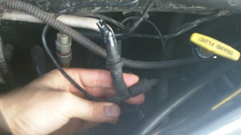
The vacuum hose system in your 4.7L Dodge engine might seem like a tangled mess of rubber, but it's actually a carefully orchestrated network crucial for optimal engine performance. Understanding its layout is vital for a variety of reasons, from diagnosing a simple rough idle to performing more complex engine repairs or even tackling performance modifications. This article provides a comprehensive guide to the 4.7L Dodge vacuum hose diagram, equipping you with the knowledge to confidently navigate this system.
Purpose of the Vacuum Hose Diagram
Why should you care about a vacuum hose diagram? The answer is multi-faceted:
- Troubleshooting Engine Problems: Vacuum leaks are notorious for causing a wide range of issues, including rough idling, poor fuel economy, hesitation, and even stalling. A diagram helps you quickly locate and identify potential problem areas.
- Repairing or Replacing Hoses: Over time, vacuum hoses can become brittle, cracked, or disconnected. The diagram allows you to accurately replace damaged hoses with the correct size and routing.
- Understanding Engine Operation: By tracing the vacuum lines, you gain a deeper understanding of how various engine components interact and how vacuum is used to control them.
- Performance Modifications: If you're planning any engine modifications, such as installing a new intake manifold or throttle body, understanding the vacuum system is essential to ensure proper operation and avoid creating vacuum leaks.
- Passing Emissions Tests: A properly functioning vacuum system is crucial for minimizing emissions. Incorrectly routed or leaking hoses can lead to failed emissions tests.
Key Specs and Main Parts
The 4.7L Dodge engine utilizes vacuum to control several important components. Here are the key parts and their relationship to the vacuum system:
- Intake Manifold: This is the central source of vacuum for the system. Engine vacuum is created as the pistons move down on the intake stroke, creating a negative pressure within the manifold.
- Vacuum Lines: These are typically rubber or silicone hoses that carry vacuum from the intake manifold to various components. Different size hoses are used depending on the application.
- PCV Valve (Positive Crankcase Ventilation): The PCV valve regulates the flow of crankcase gases back into the intake manifold for combustion. It's connected to the intake manifold via a vacuum hose. A faulty PCV valve or a leaking hose in this system can cause significant problems.
- EGR Valve (Exhaust Gas Recirculation): The EGR valve reduces NOx (nitrogen oxides) emissions by recirculating a portion of the exhaust gas back into the intake manifold. It's often controlled by a vacuum actuator.
- Brake Booster: This uses vacuum to assist the driver in applying the brakes. A large vacuum hose connects the brake booster to the intake manifold. A leak in this hose can result in hard braking.
- HVAC System: Vacuum is often used to control the various doors and actuators within the heating, ventilation, and air conditioning (HVAC) system. This controls air flow direction.
- Vacuum Reservoir: Some vehicles have a vacuum reservoir to store vacuum for use when the engine is under load and vacuum levels are low. This ensures consistent operation of vacuum-controlled accessories.
- Throttle Body: While the primary function is air intake, the throttle body often has ports for vacuum lines connecting to different components, like the EVAP system.
- EVAP System (Evaporative Emission Control): This system prevents fuel vapors from escaping into the atmosphere. It uses vacuum to purge fuel vapors from the charcoal canister and route them back into the engine for combustion.
Understanding the Vacuum Hose Diagram: Symbols and Conventions
Vacuum hose diagrams use a standardized set of symbols and conventions to represent the various components and connections. Learning these conventions will help you interpret the diagram accurately.
- Solid Lines: Typically represent vacuum hoses carrying vacuum.
- Dotted Lines: Often represent electrical wiring or control signals.
- Arrows: Indicate the direction of vacuum flow.
- Circles or Ovals: Represent vacuum-operated components, such as actuators or valves.
- Different Colors: Some diagrams use different colors to differentiate between different types of hoses or systems. For example, a blue line might represent a vacuum hose related to the EVAP system, while a green line might represent a hose related to the PCV system. However, color coding can vary between diagrams.
- Abbreviations: Diagrams often use abbreviations to label components, such as "PCV" for Positive Crankcase Ventilation, "EGR" for Exhaust Gas Recirculation, or "MAP" for Manifold Absolute Pressure sensor.
It's crucial to consult the specific vacuum hose diagram for your vehicle's year and model, as there can be variations.
How the Vacuum System Works
The 4.7L Dodge engine utilizes the vacuum created in the intake manifold to operate several crucial systems. Here's a simplified overview:
- Vacuum Creation: As the engine runs, the pistons move down on the intake stroke, creating a vacuum in the intake manifold.
- Distribution: This vacuum is then distributed through a network of vacuum hoses to various components.
- Component Operation: Vacuum-operated components use this vacuum to perform their functions. For example, the brake booster uses vacuum to assist in braking, while the EGR valve uses vacuum to open and allow exhaust gas to recirculate.
- Regulation: Vacuum is often regulated by valves or solenoids to control the amount of vacuum applied to a specific component.
The system is designed to be self-regulating. For example, the PCV valve has a calibrated orifice to limit the amount of crankcase gas that is drawn into the intake manifold, preventing the engine from running too lean.
Real-World Use: Basic Troubleshooting Tips
Here are some practical tips for troubleshooting vacuum hose problems:
- Visual Inspection: Start by visually inspecting all vacuum hoses for cracks, breaks, or disconnections. Pay close attention to areas near heat sources or sharp edges.
- The "Listen" Test: With the engine running, listen for hissing sounds, which can indicate a vacuum leak. A mechanic's stethoscope can be helpful for pinpointing the source of the leak.
- The "Spray" Test: With the engine running, carefully spray small amounts of carburetor cleaner or soapy water around vacuum hose connections. If the engine idle changes or you see bubbles forming, you've found a leak. Be extremely careful when spraying flammable liquids near a hot engine.
- Vacuum Gauge Test: A vacuum gauge can be used to measure the vacuum level in the intake manifold. A low or fluctuating vacuum reading can indicate a vacuum leak or other engine problems.
- Smoke Test: A smoke test involves introducing smoke into the vacuum system and looking for smoke escaping from leaks. This is a more advanced technique that can be very effective for finding hard-to-detect leaks.
Common Symptoms of Vacuum Leaks:
- Rough idling
- Poor fuel economy
- Hesitation or stalling
- Check engine light (CEL) with codes related to lean conditions or vacuum leaks (e.g., P0171, P0174)
- Hard braking (if the brake booster hose is leaking)
- HVAC system malfunctions
Safety Considerations
Working on the vacuum system generally isn't inherently dangerous, but there are a few safety precautions to keep in mind:
- Hot Engine Components: Be careful when working around hot engine components, such as the exhaust manifold. Allow the engine to cool down before working on the vacuum system.
- Flammable Liquids: As mentioned earlier, be extremely careful when using flammable liquids like carburetor cleaner to locate vacuum leaks. Avoid spraying near hot surfaces or ignition sources.
- Moving Parts: Keep your hands and clothing away from moving engine parts, such as the belts and pulleys.
- Battery Disconnection: While not always necessary for simple vacuum hose repairs, disconnecting the battery can provide an extra layer of safety, especially if you're working near electrical components.
The Brake Booster Hose: This is a high-vacuum line that can cause a significant safety issue if it fails. Always use high-quality replacement hose specifically designed for brake booster applications.
Remember, a thorough understanding of the 4.7L Dodge vacuum hose diagram is invaluable for maintaining and repairing your vehicle. By following the tips and guidelines outlined in this article, you can confidently diagnose and address vacuum-related issues.
We have a detailed vacuum hose diagram available for download to help you further in your troubleshooting and repair endeavors. This diagram is specific to the 4.7L Dodge engine and provides clear visuals of hose routing and component locations.