
4l60e Diagram Chevy Truck Shift Linkage
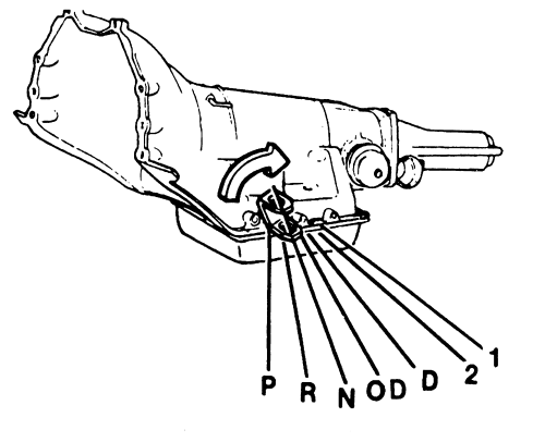
Alright, let's dive into the 4L60E shift linkage diagram for your Chevy truck. Whether you're tackling a repair, swapping out parts, or just trying to understand how your transmission communicates with the gear selector, understanding this diagram is crucial. We're going to break it down step-by-step, like I would if you were standing next to me in the shop.
Purpose of the 4L60E Shift Linkage Diagram
This diagram isn't just some pretty picture. It's your roadmap to understanding the mechanical connection between your gear selector (the shifter inside your cab) and the 4L60E transmission itself. It's invaluable for:
- Troubleshooting Shift Problems: Is your truck stuck in park? Can't get into reverse? The diagram helps you trace the path of the linkage and identify potential weak points.
- Performing Repairs: Replacing worn bushings, bent rods, or a faulty shift cable becomes much easier when you understand how everything connects.
- Modifications and Swaps: If you're swapping in a different transmission or performing a custom shifter setup, the diagram provides the foundation for understanding how to adapt your existing linkage.
- General Understanding: Even if you're not actively working on your truck, the diagram can help you appreciate the mechanics behind shifting gears.
Key Specs and Main Parts
The specific components of the shift linkage can vary slightly depending on the year and model of your Chevy truck, but the fundamental principles remain the same. Here's a breakdown of the main parts you'll see on the diagram:
- Gear Selector (Shifter): Located inside the cab, this is what you use to select the desired gear (Park, Reverse, Neutral, Drive, etc.).
- Shift Cable or Rod: This is the physical link that connects the gear selector to the transmission's manual valve. Cables offer more flexibility, while rods provide a more direct mechanical connection.
- Transmission Manual Valve: This valve, located inside the 4L60E, directs hydraulic fluid to the appropriate clutch packs and bands to engage the selected gear. The shift linkage physically moves this valve.
- Transmission Manual Shaft: The external shaft on the 4L60E that connects to the shift linkage and rotates to move the manual valve inside the transmission.
- Adjusting Trunnions/Connectors: These are usually threaded connectors that allow you to fine-tune the length of the shift linkage. Proper adjustment is crucial for accurate gear selection.
- Bushings and Pivots: These are the connection points that allow the linkage to move smoothly. They are often made of plastic or rubber and are prone to wear and tear.
- Shift Lever: Usually attached directly to the manual shaft on the transmission. The shift cable or rod connects to this lever.
Pay close attention to the specific design of your shift linkage. Is it a cable system or a rod system? Where are the adjusting points located?
Understanding Symbols in the Diagram
Diagrams use a standardized set of symbols to represent different components and their connections. Here's a general guide:
- Solid Lines: Typically represent solid components like rods, levers, and brackets.
- Dashed Lines: Often indicate flexible components like shift cables or linkages behind other components, showing they are hidden from direct view.
- Arrows: Show the direction of movement or force. In the case of the shift linkage, arrows will show the direction the cable or rod moves to achieve a specific gear selection.
- Circles and Squares: Often represent connectors, pivots, or mounting points. A filled circle might indicate a fixed pivot, while an open circle indicates a rotating pivot.
- Color Coding (If Present): Some diagrams use colors to distinguish different parts of the linkage or different systems entirely. Consult the diagram's legend for specific color meanings. If you have a diagram in color and one in black and white, you'll notice that they convey the same information.
Important: Always refer to the specific legend or key included with your diagram. Symbols can vary slightly depending on the diagram's source.
How the Shift Linkage Works
The 4L60E shift linkage is a pretty straightforward system. When you move the gear selector in the cab, the movement is transferred through the shift cable or rod to the transmission's manual shaft. This shaft then rotates the manual valve inside the transmission.
The manual valve is the key to selecting gears. It's a precisely machined valve body with passageways that direct hydraulic fluid to different clutch packs and bands within the transmission. Engaging these clutch packs and bands effectively locks certain gears together, creating the desired gear ratio.
For example, when you select "Drive," the manual valve directs fluid to the appropriate clutch packs and bands to engage first gear. As the vehicle accelerates, the transmission's internal computer (TCM) controls the automatic shifting process, using solenoids to further manipulate the flow of hydraulic fluid and change gears. However, the initial gear selection – Drive, Reverse, Park, etc. – is mechanically controlled by the shift linkage.
Real-World Use: Basic Troubleshooting Tips
Here are a few common problems you might encounter and how the shift linkage diagram can help you diagnose them:
- Difficulty Shifting into Gear: This could be caused by a misadjusted shift linkage. Use the diagram to identify the adjusting trunnions and follow the factory service manual's procedure to properly adjust the linkage. The diagram shows you exactly where to find the adjustment point.
- Slop or Play in the Shifter: Worn bushings or loose connectors in the shift linkage can cause excessive play. The diagram helps you locate these bushings and connectors for inspection and replacement.
- Stuck in Park: A broken or disconnected shift cable can prevent you from shifting out of park. Use the diagram to trace the cable's path and identify any breaks or disconnections. Check the connection at both the shifter and the transmission.
- Incorrect Gear Indication: The gear indicator on your dash might not match the actual gear the transmission is in. This is often due to a misadjusted shift linkage. The diagram will highlight the adjustment points you need to address.
Safety Considerations
Working on the shift linkage can involve a few safety hazards:
- Working Under the Vehicle: Always use jack stands when working under your truck. Never rely solely on a jack.
- Hot Exhaust: Be mindful of the exhaust system, especially if the engine has been running recently. Allow it to cool down before working in that area.
- Moving Parts: Ensure the vehicle is in park with the parking brake engaged before working on the shift linkage. Disconnect the battery to prevent accidental starting.
- Sharp Edges: Wear gloves to protect your hands from sharp edges on the linkage components.
- Potential for Fluid Leaks: Be prepared for potential transmission fluid leaks. Have a drain pan ready.
The manual shaft on the transmission is directly connected to the internal workings of the transmission. Avoid forcing it or over-rotating it, as this could damage the valve body or other internal components.
Alright, you should now have a much better understanding of the 4L60E shift linkage diagram and how it applies to your Chevy truck. Remember to always consult the factory service manual for your specific year and model. These diagrams provide a foundation, but the manual gives you the precise procedures and torque specifications you need for a successful repair.
We have a detailed, downloadable version of the 4L60E shift linkage diagram ready for you. It includes exploded views and detailed callouts. Just reach out and we can provide you with access. Happy wrenching!