4wd Actuator Chevy Front Axle Actuator Wiring
Alright, let's dive into the fascinating world of Chevy 4WD front axle actuator wiring. This isn't just about knowing which wire goes where; it's about understanding the system as a whole, which will empower you to diagnose problems, perform repairs, and even potentially modify your 4WD system with confidence. This article will provide a comprehensive overview of the wiring schematic, its components, operation, and troubleshooting tips. We've got the full diagram, and you can download it after reading through this guide.
Why This Wiring Diagram Matters
Having a solid understanding of your 4WD front axle actuator wiring is crucial for several reasons:
- Troubleshooting 4WD Engagement Issues: Is your 4WD not engaging or disengaging properly? The wiring is often the culprit. A broken wire, corroded connector, or a faulty ground can all prevent the actuator from functioning correctly.
- Performing Repairs: Replacing a damaged actuator or repairing a broken wire becomes significantly easier and more accurate when you can confidently trace the circuit and understand its function.
- Understanding System Operation: Knowing how the actuator is wired allows you to grasp the entire 4WD system's logic, from the switch on your dashboard to the actual engagement of the front axle.
- Customization and Modifications: If you're planning on adding aftermarket components, such as a manual actuator switch or a different type of locking differential, you'll need to understand the factory wiring to integrate these modifications successfully.
- Avoiding Costly Mechanic Bills: With this knowledge, you can potentially diagnose and fix the issue yourself, saving on expensive labor costs at a repair shop.
Key Specs and Main Parts
Before we delve into the wiring diagram itself, let's cover the key components involved in the front axle actuator system on a typical Chevy 4WD:
- 4WD Switch: Located on the dashboard, this switch allows you to select the desired 4WD mode (2HI, 4HI, 4LO). It sends a signal to the transfer case control module.
- Transfer Case Control Module (TCCM): The "brain" of the 4WD system. It receives input from the 4WD switch, vehicle speed sensors, and other sensors, and then sends commands to the transfer case and front axle actuator.
- Front Axle Actuator (or Electric Shift Actuator): This is the component we're focusing on. It's an electromechanical device that physically engages (or disengages) the front axle to allow power to be sent to the front wheels. It's usually mounted directly on the front axle. This is basically a small motor that moves a fork inside the axle.
- Wiring Harness: The network of wires that connects all the components together, carrying signals and power.
- Ground Points: Essential for completing the electrical circuits. A bad ground is a common cause of 4WD problems.
- Fuses: Protect the circuits from overloads. Located in the fuse box.
Actuator Types: It's worth noting that Chevy trucks and SUVs have used various types of front axle actuators over the years. The most common types are thermal actuators (older models) and electric actuators (newer models). This article primarily focuses on the wiring for the electric type, as they are more prevalent in modern vehicles and more easily diagnosed with wiring diagrams.
Understanding Wiring Diagram Symbols
To interpret the wiring diagram effectively, you need to understand the basic symbols used:
- Lines: Represent wires. The thickness of the line doesn't usually indicate wire gauge.
- Colors: Each wire has a specific color code (e.g., RED, BLK, GRN/WHT). These colors are usually abbreviated on the diagram. Always verify the color code on the actual wire before making any connections.
- Circles: Represent connections or splices in the wiring.
- Squares/Rectangles: Represent components like switches, modules, and actuators.
- Ground Symbol (usually three horizontal lines decreasing in length): Indicates a connection to the vehicle's chassis ground.
- Fuse Symbol: Represents a fuse. The amperage rating of the fuse is usually indicated nearby.
- Connector Symbols: Show where wiring harnesses connect to components. Often numbered for identification.
- Abbreviations: Diagrams often use abbreviations to represent components, wire colors, and functions (e.g., TCCM, GRN, SIG).
The diagram we provide will include a legend explaining the specific symbols and abbreviations used. The line colors are critical – for example, a GRN/WHT wire would be Green with a White stripe.
How It Works: 4WD Actuator Wiring in Action
Let's break down how the wiring enables the front axle actuator to function:
- 4WD Mode Selection: You select a 4WD mode using the switch on your dashboard.
- Signal to TCCM: The switch sends a signal to the Transfer Case Control Module (TCCM).
- TCCM Processing: The TCCM analyzes the request, taking into account vehicle speed, wheel speed sensor data, and other parameters.
- Actuator Command: If the conditions are right for 4WD engagement, the TCCM sends a command signal to the front axle actuator. This signal is typically a PWM (Pulse Width Modulation) signal, which controls the amount of voltage sent to the actuator motor.
- Actuator Engagement: The actuator motor receives the signal and rotates, moving a fork inside the front axle. This fork engages a splined collar, mechanically locking the two axle shafts together, allowing power to be sent to the front wheels.
- Feedback Signal: Many actuators have a feedback signal that reports back to the TCCM indicating whether the engagement was successful. This allows the TCCM to verify that the 4WD system is functioning correctly.
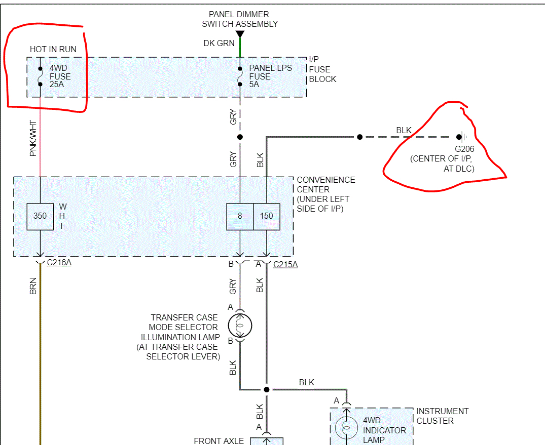
The wiring diagram will show you which wires carry the power, ground, command signal, and feedback signal to and from the actuator. Identifying these wires is critical for troubleshooting.
Real-World Use: Basic Troubleshooting Tips
Here are some basic troubleshooting steps you can take using the wiring diagram:
- Visual Inspection: Start by visually inspecting the wiring harness for any obvious signs of damage, such as cuts, frays, or corrosion. Pay close attention to the connectors.
- Check Fuses: Consult your owner's manual to identify the fuse(s) that protect the 4WD system. Check the fuses for continuity using a multimeter.
- Test for Power and Ground: Use a multimeter to verify that the actuator is receiving power and ground. Consult the wiring diagram to identify the correct pins to test.
- Check for Signal: With the vehicle in 4WD, use a multimeter or logic probe to check for a signal on the command wire from the TCCM to the actuator.
- Test Actuator Resistance: Use a multimeter to measure the resistance of the actuator motor. A very high or very low resistance reading could indicate a faulty motor.
- Scan for Codes: Use an OBD-II scanner to check for diagnostic trouble codes (DTCs) related to the 4WD system. These codes can provide valuable clues about the source of the problem. Common codes include those related to the actuator motor, the TCCM, and the wheel speed sensors.
- Ground Inspection: Remove and clean any ground points associated with the 4wd system. Bad grounds are common causes of electrical issues.
Example: Let's say your 4WD isn't engaging. You consult the wiring diagram and identify the power and ground wires to the actuator. You use a multimeter and find that there is no power reaching the actuator. This points to a problem upstream, such as a blown fuse, a broken wire, or a faulty TCCM.
Safety First!
Working with electrical systems can be dangerous. Here are some safety precautions to keep in mind:
- Disconnect the Battery: Always disconnect the negative battery cable before working on any electrical components. This will prevent accidental shorts and electrical shocks.
- Use Proper Tools: Use insulated tools designed for electrical work.
- Work in a Well-Lit Area: Good lighting will help you see what you're doing and avoid mistakes.
- Wear Safety Glasses: Protect your eyes from debris.
- Be Careful with Voltages: High voltage components, like the ignition system, can be extremely dangerous. Avoid working on these components unless you have the necessary expertise and equipment. The front axle actuator system is typically low voltage (12V), but still, be cautious.
- Don't Work Alone: It's always a good idea to have someone else present when you're working on your vehicle.
Warning: The TCCM and other electronic modules are sensitive to static electricity. Always ground yourself before touching these components.
By following these guidelines and carefully studying the wiring diagram, you'll be well-equipped to tackle many 4WD front axle actuator problems. Remember, proceed carefully, double-check your work, and don't hesitate to consult a professional if you're unsure about anything.
Ready to get your hands on the full wiring diagram? You can download it here: [Link to Diagram - Placeholder]. Good luck, and happy wrenching!