
4wd Ford F150 Front Suspension Diagram
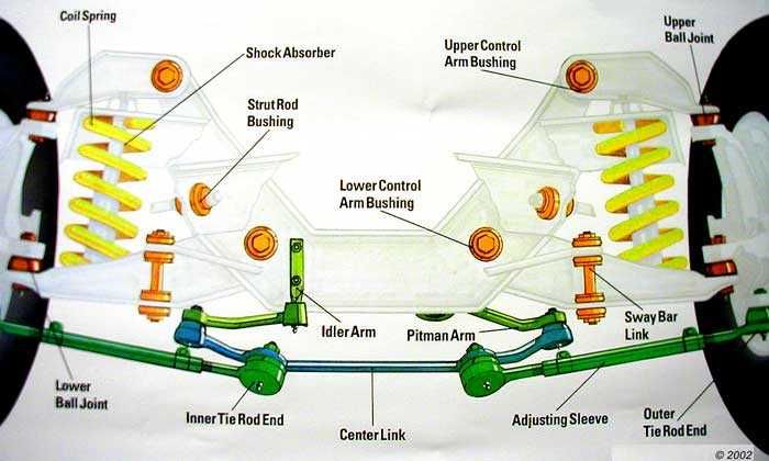
Understanding the front suspension of your 4WD Ford F-150 is crucial for maintenance, repairs, upgrades, and even just diagnosing those unsettling noises you might be hearing. A detailed suspension diagram serves as a roadmap, guiding you through the complex interplay of components that keep your truck riding smoothly and handling predictably, especially when tackling off-road terrain. This article will break down a typical 4WD F-150 front suspension diagram, focusing on its purpose, key components, functionality, and practical applications for the DIY mechanic.
Why a Suspension Diagram Matters
Why bother with a suspension diagram? Simple: It's the key to unlocking a deeper understanding of your truck. Here's why it's valuable:
- Repairs and Maintenance: A diagram pinpoints the location of parts, making it much easier to identify and replace worn or damaged components. Whether it’s a ball joint, control arm, or shock absorber, the diagram shows you exactly where it sits within the assembly.
- Troubleshooting: Diagnosing suspension issues can be tricky. A diagram helps you trace potential problems, understand the interconnectedness of parts, and identify the root cause of the issue. Is that clunking sound coming from a worn-out sway bar link or a failing upper control arm bushing? The diagram can help you narrow it down.
- Upgrades and Modifications: Planning a lift kit or upgrading to heavy-duty shocks? The diagram allows you to visualize how aftermarket components will integrate with the existing suspension system, helping you avoid compatibility issues and ensure proper installation.
- Learning and Understanding: Even if you're not planning any immediate repairs, studying the diagram will give you a better understanding of how your truck's suspension works, allowing you to appreciate the engineering that goes into providing a comfortable and capable ride.
Key Specs and Main Parts of a 4WD F-150 Front Suspension
The 4WD F-150 typically utilizes an independent front suspension (IFS) system. While variations exist across different model years and trim levels, the fundamental components remain consistent. Understanding these components is crucial for interpreting the diagram.
- Upper and Lower Control Arms: These are the primary links connecting the wheel hub to the frame. The upper control arm is usually shorter than the lower. They allow the wheel to move up and down while maintaining its alignment. Control arms are vital; damage or wear impacts handling and tire wear.
- Coil Springs: These provide the primary support for the vehicle's weight and absorb bumps and vibrations. In some models, the coil spring is integrated into the shock absorber forming a strut assembly. The spring rate is a critical specification, determining the stiffness of the suspension.
- Shock Absorbers/Struts: Dampen the oscillations of the coil springs, preventing the vehicle from bouncing excessively. They control the rate at which the suspension compresses and rebounds, contributing to ride quality and stability.
- Steering Knuckle/Spindle: This component houses the wheel hub and bearings and connects to the upper and lower control arms via ball joints. It's the pivoting point for steering.
- Ball Joints: These are spherical bearings that allow the steering knuckle to pivot, enabling steering and suspension movement. They connect the control arms to the steering knuckle. Worn ball joints are a common failure point.
- Tie Rods (Inner and Outer): Connect the steering rack to the steering knuckle, translating the steering wheel input into wheel movement.
- Sway Bar (Anti-Roll Bar): Reduces body roll during cornering, improving stability and handling. It connects to the frame and the suspension components via sway bar links.
- Sway Bar Links: Connect the sway bar to the control arms or struts. These are common wear items.
- Wheel Hub/Bearing Assembly: Allows the wheel to rotate freely.
- CV Axle (Constant Velocity Axle): Transfers power from the front differential to the front wheels. This is unique to 4WD vehicles.
- Front Differential: Distributes power to the front wheels, allowing them to rotate at different speeds during turns.
- Bump Stops: Limit the upward travel of the suspension, preventing damage from excessive compression.
Diagram Symbols and Conventions
Suspension diagrams often employ standardized symbols to represent different components and connections. Understanding these symbols is key to interpreting the diagram accurately.
- Lines: Solid lines generally represent physical connections, such as bolts or welds. Dashed lines may indicate a hidden component or a linkage that is not directly visible.
- Arrows: Indicate the direction of movement or force. For example, an arrow pointing towards a spring indicates compression.
- Hatching: Cross-hatching often indicates a cutaway view, revealing the internal structure of a component.
- Abbreviations: Common abbreviations include "UCA" for Upper Control Arm, "LCA" for Lower Control Arm, "BJ" for Ball Joint, and "CV" for Constant Velocity.
- Color Coding (if present): Some diagrams use color coding to differentiate between different systems or components. For example, red might indicate hydraulic lines, while blue might represent electrical connections. Consult the diagram's legend for specific color assignments.
It is important to note that some diagrams are simplified for clarity, while others are highly detailed, showing every nut, bolt, and washer. The level of detail depends on the diagram's purpose.
How the 4WD F-150 Front Suspension Works
The 4WD F-150 front suspension is designed to provide a balance of ride comfort, handling performance, and off-road capability. Here's a simplified explanation of how it works:
When the wheel encounters a bump, the suspension compresses. The coil spring absorbs the energy of the impact, preventing it from being transmitted directly to the chassis. The shock absorber dampens the spring's oscillations, controlling the rate at which the suspension compresses and rebounds. The control arms allow the wheel to move vertically while maintaining its alignment, ensuring that the tire remains in contact with the road surface. The ball joints allow the steering knuckle to pivot, enabling steering. The sway bar resists body roll during cornering, improving stability. The CV axle transmits power from the front differential to the wheels, allowing the vehicle to maintain traction in 4WD mode.
The independent front suspension design allows each wheel to react independently to bumps and irregularities in the road surface. This contributes to a smoother ride and better handling compared to a solid axle suspension. In 4WD mode, the front differential distributes power to both front wheels, providing increased traction in slippery conditions.
Real-World Use: Basic Troubleshooting Tips
Here are a few common suspension problems and how a diagram can help you diagnose them:
- Clunking Noise: Often indicates worn ball joints, tie rod ends, sway bar links, or control arm bushings. The diagram helps you locate these components and visually inspect them for excessive play or damage.
- Squeaking Noise: Can be caused by dry or worn bushings. The diagram helps you identify potential sources of friction.
- Excessive Bouncing: Indicates worn shock absorbers. The diagram shows you the location of the shocks and allows you to inspect them for leaks or damage.
- Uneven Tire Wear: Can be caused by misaligned suspension components, such as worn ball joints or bent control arms. The diagram helps you visualize the suspension geometry and identify potential causes of misalignment.
- Vibrations: A worn CV joint can cause vibration, and the diagram will help you locate this part.
Remember: Always consult your vehicle's service manual for specific troubleshooting procedures and torque specifications.
Safety Considerations
Working on suspension components can be dangerous due to the high forces involved. Always take the following precautions:
- Use Jack Stands: Never work under a vehicle supported only by a jack. Always use properly rated jack stands to support the vehicle securely.
- Spring Compression: Coil springs store a significant amount of energy. When disassembling a strut assembly, use a spring compressor to safely relieve the spring tension. Failure to do so can result in serious injury or death.
- Torque Specifications: Always tighten fasteners to the manufacturer's specified torque. Over-tightening can damage components, while under-tightening can lead to failure.
- Wear Safety Glasses: Protect your eyes from flying debris.
- Disconnect the Battery: While not always necessary, disconnecting the battery can prevent accidental activation of electrical components.
Working on your vehicle's suspension can be a rewarding experience, but it's crucial to prioritize safety. If you're not comfortable performing a particular task, seek professional assistance.
Now that you understand the value of 4WD Ford F-150 front suspension diagrams, you're better equipped to maintain and repair your vehicle. We have a detailed diagram file available for download to aid in your projects.