
4x4 Diagram Ford Ranger Transfer Case
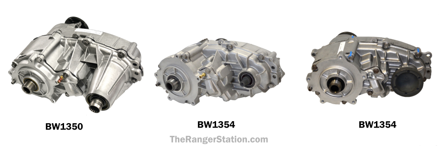
Understanding the 4x4 system in your Ford Ranger is crucial for maintenance, repairs, and even performance upgrades. A clear diagram of the transfer case is an invaluable tool for any experienced DIYer tackling these tasks. This article will guide you through interpreting such a diagram, focusing on the common electronically shifted transfer case found in many Rangers. We’ll break down the components, explain the symbols, and give you a practical understanding of how it all works. We even have the diagram file available for download, as referenced later.
Purpose of a 4x4 Transfer Case Diagram
A 4x4 transfer case diagram serves several vital purposes:
- Troubleshooting: It helps you pinpoint the source of 4x4 system issues, like grinding noises, failure to engage, or slipping.
- Repairs and Maintenance: The diagram guides you through disassembling, inspecting, and reassembling the transfer case.
- Parts Identification: It allows you to accurately identify and order replacement parts, ensuring you get the correct components.
- Understanding System Operation: Studying the diagram provides a deeper understanding of how the 4x4 system functions, allowing for more informed modifications and upgrades.
- DIY Confidence: Having a visual guide boosts confidence when tackling complex repairs, reducing the risk of errors.
Key Specs and Main Parts
Before diving into the diagram, let’s cover some key specifications and the main components of a typical Ford Ranger electronically shifted transfer case. These are general, so specific Ranger model years might have slight differences.
- Type: Part-time 4x4, electronically shifted. This means the system isn't designed for continuous 4-wheel drive on paved roads.
- Ratios: Typically a 1:1 ratio in 2Hi and a 2.48:1 or similar ratio in 4Lo. This 4Lo ratio provides significant torque multiplication for off-road situations.
Main components illustrated in the diagram include:
- Input Shaft: Connected to the transmission output shaft, receiving power from the engine.
- Output Shafts: One output shaft drives the front driveshaft, and the other drives the rear driveshaft.
- Mode Fork: Shifts between 2Hi, 4Hi, and 4Lo. Moved by an electric shift motor.
- Range Fork: Engages the low-range gears for 4Lo. Also moved by the electric shift motor.
- Sleeve: A sliding component that engages gears for different modes.
- Shift Motor: An electric motor that actuates the mode and range forks. It receives commands from the 4x4 selector switch in the cab.
- Planetary Gear Set (Low Range): Provides the gear reduction for 4Lo.
- Oil Pump: Circulates lubricant within the transfer case.
- Bearings: Support rotating shafts and minimize friction.
- Seals: Prevent lubricant leaks.
- Housing: The outer casing that contains all the components.
Understanding Diagram Symbols
Diagrams use standardized symbols to represent components and connections. Here's a breakdown of common symbols you might encounter:
- Solid Lines: Generally represent mechanical connections, like shafts or linkages. A thicker solid line often indicates a major power flow path.
- Dashed Lines: Typically represent electrical connections, vacuum lines, or fluid lines (like lubrication passages).
- Circles and Squares: These can represent various components. Look for labels or a legend on the diagram to identify them. For instance, a circle with an 'X' inside might represent a bearing.
- Arrows: Indicate direction of rotation or force. Pay attention to the direction of arrows related to the shift forks.
- Color Coding: While not always present, some diagrams use color coding to differentiate between systems or lubricant flow. A common example is red for pressurized oil and blue for return oil.
Interpreting Labels: Most diagrams have labels or callouts that point to specific parts. These labels will often use abbreviations or part numbers. Refer to a parts catalog or online resources to decipher any unfamiliar abbreviations.
How It Works
The transfer case's primary function is to split power from the transmission between the front and rear axles. Here's a simplified explanation of how it works in different modes:
- 2Hi (2-Wheel High): The transfer case sends all power to the rear output shaft. The front driveshaft is disengaged and doesn't receive power. The mode fork is positioned to direct power only to the rear output.
- 4Hi (4-Wheel High): The mode fork engages the front output shaft, splitting power between the front and rear axles. The planetary gear set is not engaged, providing a 1:1 gear ratio.
- 4Lo (4-Wheel Low): The mode fork engages the front output shaft, and the range fork engages the planetary gear set, providing a low-range gear reduction. This greatly increases torque to both axles for challenging off-road conditions. This is where the lower gearing is engaged.
The electric shift motor is responsible for moving the mode and range forks. When you select a different 4x4 mode on the dashboard switch, the truck's computer sends a signal to the shift motor. The motor rotates, moving the forks and engaging the appropriate gears within the transfer case. Sensors within the transfer case or shift motor provide feedback to the computer, confirming that the selected mode has been engaged.
Real-World Use: Basic Troubleshooting
Let's look at some common 4x4 problems and how the diagram can help:
- Problem: 4x4 indicator light flashes but doesn't engage.
Troubleshooting: Check the shift motor. The diagram shows its location and how it connects to the shift forks. Use a multimeter to check for power at the shift motor connector. If there's power but the motor isn't moving, the motor might be faulty. Also, check the shift motor position sensor signal. A faulty sensor will prevent proper engagement.
- Problem: Grinding noise when engaging 4x4.
Troubleshooting: This could indicate worn gears or a damaged shift fork. The diagram will allow you to see how the gears mesh. Visually inspect the gears for wear or damage when you drain the fluid. A bent or broken shift fork won't properly engage the gears, causing grinding.
- Problem: Leaking transfer case fluid.
Troubleshooting: The diagram shows the location of all seals and gaskets. Identify the source of the leak by visually inspecting around these areas. Common leak points include the input shaft seal, output shaft seals, and the case halves.
Safety Considerations
Working on a transfer case involves several safety risks:
- Heavy Components: The transfer case itself is heavy. Use a jack or transmission jack to support it during removal and installation. Never work under a vehicle supported only by a jack. Use jack stands.
- Sharp Edges: The transfer case housing and internal components can have sharp edges. Wear gloves to protect your hands.
- Flammable Fluids: Transfer case fluid is flammable. Keep open flames away from the work area. Clean up any spills immediately.
- Electrical Components: The shift motor and wiring harness involve electrical connections. Disconnect the battery before working on any electrical components to prevent short circuits and potential shocks.
- High Pressure: Although not typically pressurized internally, some systems may have accumulators or high-pressure lubrication circuits. Consult the service manual before disassembling to identify and safely depressurize these components.
Note: Always consult your Ranger's service manual for specific procedures and torque specifications.
By carefully studying the transfer case diagram and following proper safety procedures, you can confidently diagnose and repair many 4x4 system problems. Remember, if you're uncomfortable with any aspect of the repair, it's always best to consult a qualified mechanic.
We have the Ford Ranger 4x4 Transfer Case Diagram readily available. Please contact us through the appropriate channels (support email, website form, etc.) to request the file. Make sure to specify the year and model of your Ranger for the most accurate diagram.