5 Pin Ignition Switch Wiring Diagram
Let's dive into the world of 5-pin ignition switch wiring diagrams. If you're someone who likes to tinker with cars, modify electrical systems, or even just understand how your vehicle starts, knowing how to read and interpret these diagrams is invaluable. This article will break down the essentials, from the purpose of the diagram to real-world troubleshooting, ensuring you can confidently work with your car's ignition system.
Purpose of a 5-Pin Ignition Switch Wiring Diagram
A 5-pin ignition switch wiring diagram is essentially a roadmap of the electrical connections within your vehicle's ignition system. Its main purpose is to provide a clear, visual representation of how the ignition switch interacts with other crucial components like the battery, starter motor, and various accessory circuits. Why is this important? Consider these scenarios:
- Repairs: When your car refuses to start or exhibits strange electrical behavior, the ignition switch is often a prime suspect. The diagram allows you to pinpoint wiring faults, such as shorts, open circuits, or damaged connectors, quickly and efficiently.
- Modifications: Planning to install an aftermarket alarm system, remote starter, or even a custom gauge cluster? Understanding the ignition switch wiring is crucial to tap into the correct circuits without causing damage or malfunctions.
- Learning and Diagnostics: Gaining a deeper understanding of automotive electrical systems is a rewarding experience. The ignition switch is a central hub, and analyzing its wiring diagram is a great starting point for learning about the overall operation of your vehicle.
- Restoration: Working on a classic car? Original wiring diagrams can be scarce or inaccurate. Understanding the 5-pin ignition switch configuration allows you to reverse-engineer the system and ensure proper wiring during restoration.
Key Specs and Main Parts
Before we dissect the diagram, let's define the key components and their typical functions. Keep in mind that specific wiring configurations can vary between vehicle makes and models, but the fundamental principles remain the same.
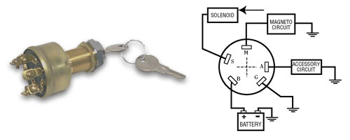
- Ignition Switch: The heart of the system, the ignition switch has multiple positions (OFF, ACC, ON, START) that activate different circuits.
- Battery (BATT): Provides the main power source for the entire vehicle. The ignition switch needs a direct connection to the battery to function.
- Accessory (ACC): Powers non-essential electrical components like the radio, wipers, and climate control system. This circuit is typically active in the ACC and ON positions.
- Ignition (IGN): Powers the engine management system, fuel pump, and other vital components necessary for the engine to run. This circuit is active in the ON and START positions.
- Starter (START): Activates the starter motor, which cranks the engine. This circuit is only active in the START position.
- Ground (GND): Provides a return path for the electrical current. A good ground connection is essential for proper circuit operation.
While technically a 5-pin switch only has 5 connections, some wiring diagrams might include additional wires connected to each pin, controlling relays or other functions. Don't be alarmed by this; focus on tracing the primary wires first.
Symbols in the Diagram
Understanding the symbols used in the wiring diagram is crucial for accurate interpretation. Here's a breakdown of common symbols:
- Lines: Lines represent wires. Thicker lines often indicate wires carrying higher current. Dashed lines can represent wires on a different layer of the harness, or sometimes, optional circuits.
- Colors: Wire colors are typically indicated by abbreviations (e.g., RD for red, BLK for black, BLU for blue, YEL for yellow, GRN for green). These colors are standardized across the automotive industry.
- Connectors: Represented by circles, squares, or other shapes, connectors indicate points where wires are joined together. Pay attention to connector pin numbers, as this is how you identify specific wires.
- Fuses: Indicated by a zigzag line inside a rectangle, fuses protect circuits from overcurrent. Their amperage rating is usually specified.
- Relays: Relays are switches controlled by an electrical signal. They are represented by a coil symbol and a switch contact symbol. They are very common in modern vehicles and often used in the starter circuit.
- Ground Symbol: Typically represented by a series of downward-pointing lines, the ground symbol indicates a connection to the vehicle's chassis (ground).
Crucially, look for a legend or key on the diagram itself. This legend will define any non-standard symbols or abbreviations used in that particular diagram.
How It Works: A Circuit-by-Circuit Explanation
Let's walk through how each circuit is activated as you turn the ignition key:
- OFF: In the OFF position, no circuits are active. The ignition switch is effectively disconnected from the battery.
- ACC: When you turn the key to ACC, the accessory circuit is energized. This provides power to the radio, wipers, and other convenience features. The IGN and START circuits remain off. This reduces the electrical load on the battery before starting the engine.
- ON: Turning the key to ON activates the ignition circuit. This provides power to the engine management system, fuel pump, and other critical components required for the engine to run. The starter circuit remains off.
- START: When you turn the key to the START position, the starter circuit is energized. This sends power to the starter solenoid, which engages the starter motor and cranks the engine. Simultaneously, the ignition circuit remains powered, ensuring the engine continues to run after it starts. Once the engine starts and you release the key, it springs back to the ON position.
The internal construction of the ignition switch is complex. It uses a series of contacts that make and break connections in different combinations as the key is turned. Understanding this sequence is critical for troubleshooting starting problems.
Real-World Use: Basic Troubleshooting Tips
Now, let's apply this knowledge to some common troubleshooting scenarios:
- No Crank, No Start: If the engine doesn't crank when you turn the key to START, check the following:
- Battery Voltage: Ensure the battery has sufficient voltage (typically around 12.6 volts).
- Starter Circuit: Use a multimeter to check for voltage at the starter solenoid when the key is in the START position. If there's no voltage, the problem could be in the ignition switch, the wiring between the switch and the solenoid, or a faulty starter relay.
- Ground Connection: Verify that the starter motor has a good ground connection to the chassis.
- Crank, No Start: If the engine cranks but doesn't start, the issue likely lies in the ignition or fuel system. Use the wiring diagram to trace the ignition circuit and check for voltage at the ignition coil or fuel pump when the key is in the ON position.
- Accessories Don't Work: If the accessories don't work in the ACC position, check the fuse for the accessory circuit. If the fuse is good, use a multimeter to check for voltage at the accessory terminal of the ignition switch when the key is in the ACC position.
- Parasitic Draw: A parasitic draw is when a circuit is drawing power even when the vehicle is off. A faulty ignition switch can sometimes cause this. You can diagnose this issue by using a multimeter to measure the current draw on the battery with the ignition off and then systematically disconnecting circuits to isolate the source of the draw.
Always use a multimeter to perform voltage and continuity tests. A test light can be useful for quick checks, but a multimeter provides more accurate and detailed information.
Safety Precautions
Working with automotive electrical systems can be dangerous if you're not careful. Here are some crucial safety precautions:
- Disconnect the Battery: Before working on any electrical components, always disconnect the negative battery cable. This will prevent accidental shorts and potential damage to the electrical system.
- Avoid Working Alone: It's always a good idea to have someone nearby when working on your car, especially if you're dealing with electrical components.
- Use Insulated Tools: Use tools with insulated handles to prevent electric shock.
- Be Aware of Airbags: The airbag system is a high-voltage system that can be dangerous if triggered accidentally. If you're working near the airbag system, be sure to disconnect the battery and wait at least 30 minutes before proceeding.
- Fuel Lines: Be aware of fuel lines and fuel injectors when working in the engine bay. Ignition issues can sometimes flood the engine.
The battery and starter circuit are particularly risky due to the high currents involved. A short circuit in these areas can cause sparks, fires, and even explosions.
Understanding the 5-pin ignition switch wiring diagram empowers you to diagnose and repair electrical issues in your vehicle. By grasping the principles outlined in this article, you're well on your way to becoming a more confident and capable DIY mechanic.
We have a detailed 5-pin ignition switch wiring diagram file available for download. This diagram includes color-coded wiring and clear labels for all components, making it an invaluable tool for your automotive projects. Contact us if you'd like a copy.