
5 Pin Relay Wiring Diagram For Lights
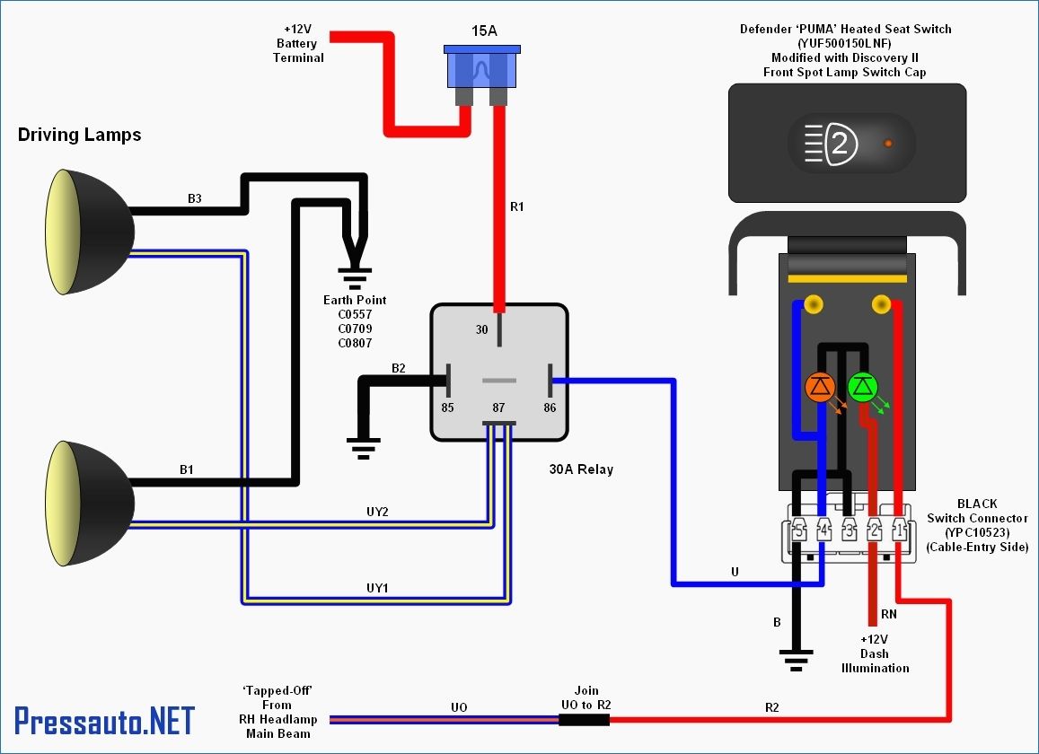
Alright, let's dive into the world of 5-pin relays and how to wire them up for controlling lights. This isn't just about blindly following a diagram; it's about understanding the *why* behind each connection. Whether you're adding auxiliary lights to your rig, upgrading your headlights, or troubleshooting a lighting issue, grasping the fundamentals of a 5-pin relay is crucial. We're talking about improved reliability, safety, and performance for your electrical system.
Purpose: Mastering the 5-Pin Relay for Lighting
Why bother learning this? Well, a 5-pin relay allows you to use a low-current circuit (like your light switch) to control a high-current circuit (the actual lights). This is vital because directly wiring high-power lights through a standard switch can overload it, leading to failure, melted wiring, or even a fire hazard. Relays act as electrically controlled switches, isolating and protecting your sensitive components while providing a robust power source for your lights. This knowledge isn't just for repairs; it's about understanding how your vehicle's electrical system functions, enabling you to confidently modify and upgrade it.
Key Specs and Main Parts
Before we get to the wiring diagram, let's break down the key specs and components of a typical 5-pin relay:
- Coil Voltage: This specifies the voltage required to energize the relay's coil, usually 12VDC in automotive applications.
- Contact Rating: This indicates the maximum current (in Amperes, or Amps) that the relay's contacts can safely switch. Make sure this rating is higher than the total current draw of the lights you're controlling. For example, if you have two 55W headlights on a 12V system, the current draw is approximately 9 Amps (Watts / Volts = Amps), so you'd want a relay rated for at least 10 Amps. A 30A or 40A relay is a common choice for automotive lighting.
- Normally Open (NO) Contact: This is the contact that is open (no connection) when the relay coil is de-energized. When the relay is activated, this contact closes, allowing current to flow.
- Normally Closed (NC) Contact: This contact is closed (connection made) when the relay coil is de-energized. When the relay is activated, this contact opens, breaking the circuit. Not always used in lighting applications, but available in a 5-pin relay.
Now, let's identify the main parts of the relay itself. You'll find these numbers printed on the relay body itself:
- Pin 30: This is the common terminal, and it's typically connected directly to the battery or a fused power source.
- Pin 87: This is the Normally Open (NO) terminal. Power flows from pin 30 to pin 87 when the relay is energized. This is typically connected to your lights.
- Pin 87a: This is the Normally Closed (NC) terminal. Power flows from pin 30 to pin 87a when the relay is NOT energized. This pin is optional and often left unconnected for basic lighting circuits.
- Pin 85: One side of the relay coil. This terminal connects to ground.
- Pin 86: The other side of the relay coil. This terminal connects to your switch (the positive side of the control circuit).
Symbols: Decoding the Wiring Diagram
Understanding the symbols used in a wiring diagram is key to successful implementation. Here's a breakdown:
- Solid Lines: Represent wires. The thickness of the line doesn't necessarily correlate with wire gauge, but it's good practice to use thicker wires for higher current circuits.
- Dotted Lines: Can represent optional connections or grounds.
- Battery Symbol: Represents the vehicle's battery, the primary power source.
- Switch Symbol: Represents the on/off switch that controls the relay.
- Relay Symbol: A box with the pin numbers labeled. Inside the box, you'll see a coil (representing the electromagnet) and a switch mechanism (showing how the contacts change state when the coil is energized).
- Light Bulb Symbol: Represents the light(s) being controlled.
- Fuse Symbol: A critical safety component! Always include a fuse in the power wire (Pin 30) as close to the battery as possible to protect the circuit from overcurrent.
- Color Codes: Wires are often color-coded. Common colors include:
- Red: Typically used for positive (+) power.
- Black: Typically used for ground (-).
- Blue/Yellow/White/etc.: Used for signal or control wires. Check the specific diagram for the exact function of each color.
How It Works: From Switch to Light
Let's walk through the sequence of events when the circuit is activated:
- You flip the switch (connected to pin 86).
- This sends a small current through the relay's coil (connected to pins 85 and 86).
- The energized coil creates an electromagnetic field, which pulls the relay's internal switch mechanism.
- This action connects pin 30 (power from the battery) to pin 87 (connected to the lights).
- Power flows through the wiring to your lights, illuminating them.
- When you turn off the switch, the coil is de-energized, the internal switch returns to its original position, and the lights turn off.
If you were using pin 87a (the normally closed contact), the lights would be on until the relay is energized. Then, when the relay energizes, the lights turn off.
Real-World Use: Troubleshooting Tips
So, you've wired everything up, and the lights aren't working. What now? Here's a basic troubleshooting checklist:
- Check the Fuse: This is the first and most obvious step. A blown fuse is a common cause of failure. Replace it with a fuse of the same amperage rating.
- Verify the Ground: Ensure that pin 85 has a solid connection to a good ground point on the vehicle's chassis. A poor ground can cause intermittent or no operation. Use a multimeter to check continuity between pin 85 and the negative terminal of the battery.
- Test the Relay: You can test the relay itself by applying 12V to pins 85 and 86. You should hear a "click" sound as the relay engages. You can also use a multimeter to check for continuity between pins 30 and 87 when the relay is energized.
- Inspect the Wiring: Look for any loose connections, frayed wires, or corrosion. Pay particular attention to crimp connectors, as these can sometimes fail.
- Test the Switch: Use a multimeter to ensure that the switch is properly sending power to pin 86 when it's in the "on" position.
- Voltage Drop Testing: Use a multimeter to measure voltage drop across the positive and negative sides of the circuit while the lights are on. Excessive voltage drop indicates resistance in the wiring or connections.
Safety: Proceed with Caution
Working with automotive electrical systems can be dangerous. Here are some crucial safety precautions:
- Disconnect the Battery: Always disconnect the negative terminal of the battery before working on any electrical components. This prevents accidental short circuits.
- Use Properly Insulated Tools: Use tools with insulated handles to protect yourself from electric shock.
- Choose the Right Wire Gauge: Use appropriate wire gauge for the current draw of your lights. Undersized wire can overheat and cause a fire. Refer to a wire gauge chart for recommended sizes.
- Protect Wires: Use wire loom or other protective coverings to protect wires from abrasion and heat.
- Double-Check Your Work: Before reconnecting the battery, carefully review your wiring to ensure that everything is connected correctly.
- Fuses are CRITICAL: Never bypass or use a higher amperage fuse than specified. Fuses are designed to protect the circuit; bypassing them can lead to catastrophic failure and fire.
Risky Components: The battery, the main power wires connected to the battery, and any high-current wires leading to the lights themselves carry a significant amount of energy. Always handle these components with extreme caution. A short circuit in these areas can result in sparks, heat, and potential burns.
This information should provide a solid foundation for understanding and working with 5-pin relays for lighting. Remember, safety is paramount. Take your time, double-check your work, and don't hesitate to consult with a qualified electrician if you're unsure about anything.
We have a detailed wiring diagram file available for download to further assist you with your project. It includes color-coded diagrams and step-by-step instructions.