
5 Pin Relay Wiring Diagram With Switch
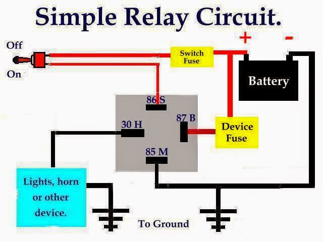
So, you're looking to wire up a 5-pin relay with a switch, huh? Excellent choice. Knowing how to handle these components opens up a world of possibilities for modifying your car's electrical system, adding aftermarket accessories, or even just fixing a pesky problem. This article will walk you through the process, covering everything from the fundamental principles to practical troubleshooting. We're aiming for a clear understanding, so you can confidently tackle this project.
Purpose of Understanding a 5-Pin Relay Wiring Diagram
Why bother learning this stuff? Well, a solid grasp of a 5-pin relay wiring diagram is invaluable for several reasons:
- Repairs: Relays fail. Understanding the diagram allows you to diagnose a malfunctioning relay and replace it correctly.
- Modifications: Adding accessories like fog lights, horns, or high-powered lights almost always requires a relay to prevent overloading your existing circuits.
- Customization: You might want to create a custom circuit for a unique feature in your car. Relays are essential for controlling these circuits safely and efficiently.
- Learning: Understanding relay operation provides a solid foundation for understanding automotive electrical systems as a whole.
Essentially, mastering this diagram empowers you to diagnose, repair, and modify your vehicle's electrical system with confidence and safety.
Key Specs and Main Parts of a 5-Pin Relay
Before diving into the diagram, let's familiarize ourselves with the components involved:
- Relay: An electrically operated switch. It allows a low-current circuit to control a high-current circuit.
- 5-Pin Relay: A specific type of relay with five terminals, each serving a distinct purpose.
- Switch: A device used to open or close a circuit, controlling the flow of electricity.
- Power Source: Typically your car's battery, providing the electrical energy.
- Load: The device being powered by the relay (e.g., fog lights, horn, etc.).
- Wiring: The conductive pathways for electrical current. Always use appropriately sized wire for the amperage.
Now, let's look at the specifications of the relay itself. Relays are usually rated by their voltage (typically 12V in automotive applications) and their amperage. The amperage rating indicates the maximum current the relay's contacts can safely handle. Exceeding this rating can damage the relay and potentially create a fire hazard. Always choose a relay with an amperage rating higher than the load's current draw.
The 5-Pin Relay specifically has these terminals:
- Pin 30: Common (Normally Open or Normally Closed connection).
- Pin 85: Relay Coil Ground.
- Pin 86: Relay Coil Power.
- Pin 87: Normally Open (NO) Contact.
- Pin 87a: Normally Closed (NC) Contact.
Understanding the Symbols in the Wiring Diagram
A wiring diagram is a visual representation of an electrical circuit. Understanding the symbols is crucial for interpreting the diagram correctly.
- Lines: Represent wires. Thicker lines often indicate wires carrying higher current.
- Circles: Can represent various components, often with a letter or abbreviation inside to identify them.
- Rectangles: Commonly represent switches, fuses, or other electrical devices.
- Zigzag Line: Represents a resistor or a load, such as a light bulb.
- Relay Symbol: A coil symbol (usually a loop or rectangle with a diagonal line through it) represents the relay's coil, and a switch-like symbol represents the relay's contacts.
Color coding is also important. While there's no universal standard in older cars, modern vehicles often use standardized color codes to identify wire functions. Common colors include:
- Red: Typically represents positive (+) power.
- Black: Typically represents ground (-).
- Yellow: Often used for switched power or accessory circuits.
- Blue: May indicate a signal wire or a wire connected to a specific sensor.
Always consult your vehicle's specific wiring diagram for accurate color coding information.
How It Works: The Relay Circuit
Let's break down the operation of a 5-pin relay with a switch. Imagine the relay as an intermediary between a small control circuit (the switch and the relay coil) and a larger, more powerful circuit (the load, like your fog lights).
- The Control Circuit: When you flip the switch to the "on" position, you complete the circuit between the power source (typically the battery) and the relay's coil (pins 85 and 86).
- The Relay Activation: Energizing the coil creates an electromagnetic field. This magnetic field pulls a small metal arm inside the relay.
- Contact Switching: This arm physically moves the common contact (pin 30). In a typical configuration, the common contact is either connected to the Normally Closed (NC) contact (pin 87a) or the Normally Open (NO) contact (pin 87).
- Powering the Load: When the relay is *not* energized, pin 30 is connected to pin 87a. When the relay *is* energized, pin 30 is connected to pin 87. In most applications, the load is connected to pin 87. So, the load only receives power when the switch is turned on and the relay is activated.
Think of it like a domino effect. The switch activates the relay coil, and the relay coil activates the load circuit.
Real-World Use and Basic Troubleshooting
Let's say you're installing fog lights. You'd wire the switch to control the relay coil. The relay would then switch the high-current power to the fog lights directly from the battery. This prevents the small switch in your dashboard from having to handle the high current of the fog lights, which could damage the switch or even cause a fire.
Troubleshooting Tips:
- No Power to the Load: Check the fuse in the load circuit. Verify the relay coil is receiving power when the switch is on. Check the relay itself by swapping it with a known good relay or testing it with a multimeter.
- Relay Clicking but No Power: The relay coil is working, but the contacts might be corroded or damaged. Replace the relay.
- Relay Constantly On: The relay coil might be shorted to ground. Check the wiring and the switch for any shorts.
Using a multimeter to check for voltage and continuity is essential for effective troubleshooting. A simple test light can also be helpful for checking for power at various points in the circuit.
Safety Considerations
Working with automotive electrical systems can be dangerous. Here are some crucial safety precautions:
- Disconnect the Battery: Always disconnect the negative terminal of your car's battery before working on any electrical circuits. This prevents accidental shorts and potential shocks.
- Proper Wire Sizing: Use appropriately sized wire for the amperage of the circuit. Undersized wire can overheat and cause a fire.
- Fuses: Always use fuses to protect the circuit. Choose a fuse rating that is slightly higher than the load's normal current draw.
- Insulation: Ensure all connections are properly insulated to prevent shorts. Use heat shrink tubing or electrical tape to cover exposed wires.
- Grounding: Ensure all ground connections are secure and clean. A poor ground connection can cause erratic behavior or even damage components.
- Relay Amperage Rating: Never exceed the relay's amperage rating. This is critical!
Disclaimer: Automotive electrical systems can be complex. If you're not comfortable working with electricity, consult a qualified professional. Incorrect wiring can damage your vehicle and potentially create a safety hazard.
By understanding the 5-pin relay wiring diagram and following these safety guidelines, you can confidently and safely modify and repair your vehicle's electrical system. We have a detailed diagram available for download, which you can use as a reference for your projects. This diagram includes common wiring configurations and troubleshooting tips.