
5 Wire Door Lock Actuator Wiring Diagram
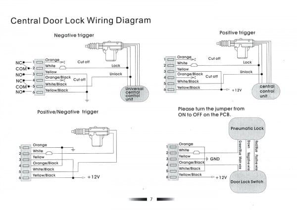
So, you're diving into the intricate world of 5-wire door lock actuators, eh? Smart move. Understanding how these systems work and how to wire them correctly opens up a whole realm of DIY possibilities, from diagnosing frustrating door lock issues to tackling custom car projects. This article isn't just about diagrams; it's about empowering you with the knowledge to confidently navigate these electrical systems.
Why Bother Understanding the 5-Wire Door Lock Actuator Wiring Diagram?
Let's be real: your door locks are essential. When they fail, it's a major inconvenience, and paying a mechanic can sting. But more than that, understanding the 5-wire system provides a solid foundation for working with various automotive electrical components. This knowledge is invaluable if you are looking to:
- Troubleshoot and fix malfunctioning door locks yourself, saving money on labor costs.
- Install aftermarket alarm systems or remote start systems that integrate with your vehicle's door locks.
- Upgrade your vehicle with power door locks if it didn't come with them originally.
- Learn about automotive electrical systems in general, which is crucial for any DIY mechanic or car enthusiast.
Key Specs and Main Parts of the 5-Wire Actuator System
Before we delve into the diagram itself, let's familiarize ourselves with the key components. This will make the wiring diagram much easier to decipher.
The Door Lock Actuator
This is the heart of the system. It's a small electric motor connected to a series of gears that physically move the door lock mechanism. It's the part that *actually* locks and unlocks your door. In a 5-wire system, the actuator receives commands from the central locking system to either lock or unlock the door.
The Central Locking Control Module
Think of this as the brains of the operation. It receives signals from your key fob, door switches, or alarm system and then sends the appropriate signals to the door lock actuators to lock or unlock the doors. It contains a microcontroller, relays, and other electronic components.
The Door Lock Switches
These are the physical switches located on your door panels. Pressing one of these switches sends a signal to the central locking control module, telling it to lock or unlock the doors. These switches can be simple on/off switches or more complex rocker switches.
Wiring Harness and Connectors
The wiring harness is the network of wires that connects all the components together. Connectors are used to easily disconnect and reconnect the various components. Proper wiring is absolutely crucial for the system to function correctly. Poor connections or damaged wires can lead to all sorts of problems.
Key Specifications
- Voltage: Typically 12V DC, supplied by the car's electrical system.
- Actuator Resistance: This is a small resistance of the motor inside the actuator, usually measured in Ohms.
- Wire Gauge: The thickness of the wires is important for carrying the current required to operate the actuator. Usually 18-22 AWG.
Decoding the 5-Wire Door Lock Actuator Wiring Diagram: Symbols and Colors
The wiring diagram is a roadmap for the electrical system. Understanding the symbols and conventions used in the diagram is essential for proper interpretation.
Common Symbols
- Solid Lines: Represent wires. A thicker line usually indicates a higher current-carrying capacity.
- Dashed Lines: Might indicate shielded cables or wires that are part of a larger harness and don't directly connect to the actuator.
- Circles: Usually represent connection points or terminals.
- Rectangles: Can represent relays, switches, or the central locking control module.
- Motors: Symbolized by a circle with an "M" inside.
- Ground: Represented by a series of horizontal lines decreasing in size. It's the return path for the electrical current.
Wire Colors
Color coding is crucial for identifying wires. Here are some common colors and their typical functions (but always verify with your specific vehicle's wiring diagram!):
- Red: Often used for positive (+) power supply.
- Black: Usually designates ground (-).
- Blue: Lock signal.
- Green: Unlock signal.
- White: Could be a common wire or a signal wire.
How the 5-Wire Door Lock Actuator System Works
The 5-wire system uses polarity reversal to control the actuator. Here's the basic process:
- Idle State: In the resting state, the central locking control module typically doesn't send any voltage to the lock or unlock wires.
- Locking: When you activate the locking mechanism (via key fob, door switch, or alarm system), the control module sends a positive voltage to the "lock" wire and grounds the "unlock" wire. This causes the actuator motor to turn in one direction, moving the door lock to the locked position.
- Unlocking: When you activate the unlocking mechanism, the control module reverses the polarity. It sends a positive voltage to the "unlock" wire and grounds the "lock" wire. This reverses the direction of the motor, moving the door lock to the unlocked position.
- The Common Wire: This wire provides a constant ground connection for the actuator motor.
Essentially, by switching the polarity on two of the wires, the control module can control the direction of the actuator motor. The other wires are for power and the signal/status of lock or unlock.
Real-World Use: Basic Troubleshooting
Okay, so your door lock isn't working. Here's a basic troubleshooting process using your understanding of the 5-wire system:
- Check the Fuse: This is the first and easiest step. Locate the fuse for the power door locks in your vehicle's fuse box and check if it's blown. Replace if necessary.
- Inspect the Wiring: Look for any obvious signs of damage, such as frayed wires, loose connections, or corrosion. Pay close attention to the wiring near the door hinges, as this area is prone to wear and tear.
- Test the Actuator: Disconnect the actuator and use a multimeter to check for voltage when you activate the lock or unlock mechanism. If you're not getting any voltage, the problem likely lies with the central locking control module, the wiring harness, or the door switches.
- Bypass Test: Apply 12V DC directly to the actuator wires (observing polarity!) to see if the actuator itself is functioning. If the actuator works when directly powered, then the issue isn't the actuator itself, but rather the signal being sent to it.
- Door Switch Testing: Use a multimeter to check the continuity of the door switches. These switches can fail over time, preventing the signal from reaching the control module.
Important: A multimeter is your best friend. Learn how to use it to check for voltage, continuity, and resistance. Always consult your vehicle's specific wiring diagram before probing any wires.
Safety First: Handling Electrical Components
Working with automotive electrical systems can be dangerous if you're not careful. Here are some crucial safety precautions:
- Disconnect the Battery: This is paramount. Disconnect the negative terminal of your car battery before working on any electrical components. This will prevent accidental shorts and electrical shocks.
- Use Insulated Tools: Use tools with insulated handles to protect yourself from electric shock.
- Be Mindful of Airbags: Some wiring for door locks may run near airbag sensors or modules. Be extremely cautious when working in these areas, as accidental activation of an airbag can cause serious injury. Refer to your vehicle's service manual for proper airbag disabling procedures if needed.
- Double-Check Your Work: Before reconnecting the battery, carefully double-check all your wiring connections to ensure they are correct and secure.
Warning: Incorrect wiring can damage your vehicle's electrical system or even cause a fire. If you're unsure about any aspect of the wiring, consult a qualified automotive electrician.
This article provides a general overview of 5-wire door lock actuator wiring. Remember that specific wiring configurations may vary depending on your vehicle's make and model. Always consult your vehicle's factory service manual or a reliable wiring diagram database for accurate information.
We've got the generalized version of the wiring diagram file ready for you. You can download it to have a handy visual aid while you work.