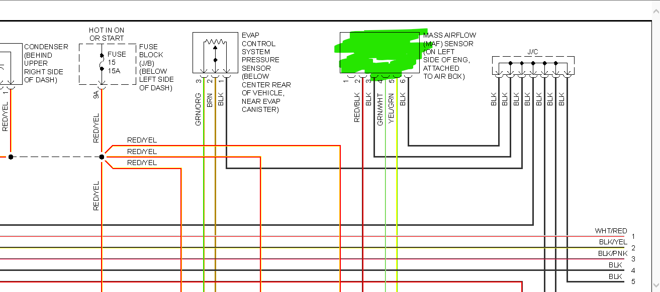
5 Wire Mass Air Flow Sensor Wiring Diagram
Alright, let's dive into the wiring diagram for a 5-wire Mass Air Flow (MAF) sensor. If you're tackling engine diagnostics, modifications, or just expanding your automotive knowledge, understanding this sensor is crucial. We're talking about a critical component that directly impacts your engine's performance, fuel efficiency, and emissions. Being able to read and understand its wiring diagram empowers you to troubleshoot issues accurately and efficiently.
Purpose of Understanding the 5-Wire MAF Wiring Diagram
Why bother with a wiring diagram? Well, a MAF sensor malfunction can manifest in various ways: poor acceleration, rough idling, stalling, decreased fuel economy, or even a Check Engine Light illuminating on your dash. The wiring diagram is your roadmap. It allows you to:
- Diagnose Electrical Issues: Pinpoint broken wires, shorts, or open circuits that can disrupt the sensor's operation.
- Verify Sensor Function: Check voltage and resistance values at specific pins to ensure the sensor is operating within its acceptable range.
- Perform Custom Wiring: If you're modifying your vehicle (e.g., swapping in a different engine or installing aftermarket components), you'll need to understand the wiring to ensure proper integration.
- Avoid Costly Repairs: Identifying and fixing a wiring issue yourself can save you a significant amount of money compared to taking your car to a mechanic.
- Deepen Your Understanding: Gaining a solid understanding of how your car's systems work builds confidence and allows you to perform more complex repairs and modifications down the road.
Key Specs and Main Parts of a 5-Wire MAF Sensor
The 5-wire MAF sensor typically incorporates both a sensor element to measure airflow and an Intake Air Temperature (IAT) sensor, combined into one unit. This is a common configuration for more modern vehicles, designed to improve efficiency and reduce component count. Let's break down the key parts:
- Hot-Wire/Hot-Film Anemometer: This is the core of the MAF sensor. A heated wire or film is exposed to the incoming airflow. The airflow cools the wire/film, and the sensor measures the amount of current required to maintain a constant temperature. This current is directly proportional to the mass airflow.
- IAT (Intake Air Temperature) Sensor: Usually a thermistor (a resistor whose resistance changes with temperature), this measures the temperature of the incoming air. This data is crucial for the ECU to calculate air density accurately and adjust fuel delivery accordingly.
- Sensor Housing: The physical body of the sensor, designed to be mounted in the intake duct. It houses the sensing elements and provides connections for the wiring harness.
- Connector: This is where the wiring harness plugs into the sensor. The pinout (the specific arrangement of wires within the connector) is critical for proper operation.
Here's a general breakdown of what each wire usually does (but always verify with your specific vehicle's wiring diagram!):
- Power (12V or 5V): Provides the necessary voltage to operate the sensor.
- Ground: Provides a reference point for the electrical circuit.
- MAF Signal: This is the output signal from the airflow sensor, usually a voltage that varies with the amount of airflow. This signal is sent to the Engine Control Unit (ECU).
- IAT Signal: This is the output signal from the IAT sensor, also usually a voltage that varies with the air temperature. This too, is sent to the ECU.
- IAT Ground (or Shared Ground): May be a separate ground for the IAT sensor or a shared ground with the MAF sensor.
Symbols, Lines, Colors, and Icons in a Wiring Diagram
Wiring diagrams are like maps for electrical circuits. Understanding the symbols is key to navigating them. Here's a basic rundown:
- Solid Lines: Represent wires. The thickness might indicate wire gauge (thicker lines for higher current carrying capacity).
- Dotted Lines: Often represent shielded wires or ground connections. Shielded wires protect the signal from electromagnetic interference.
- Colors: Each wire is typically assigned a color code (e.g., RED, BLK, GRN, YEL). This is crucial for identifying the correct wire in the harness. Wiring diagrams usually have a legend that decodes the color abbreviations.
- Connectors: Represented by various symbols, often a circle or rectangle with lines leading into it. The connector's number and pin numbers are usually labeled.
- Ground Symbols: Indicate a connection to the vehicle's chassis ground.
- Component Symbols: The MAF sensor itself might be represented by a schematic symbol showing its internal components (resistors, transistors, etc.). The IAT sensor is usually represented by a resistor symbol with a "T" for temperature.
- Voltage Sources: Represented by a plus sign (+) with a voltage value (e.g., +12V, +5V).
Understanding Wire Colors: While not universally standardized, some common color codes include:
- Red: Often used for power supply wires.
- Black: Typically used for ground wires.
- Yellow: Often used for sensor signal wires.
- Green: Sometimes used for sensor signal wires or ground wires.
- Blue: Can be used for various signals, including sensor signals.
Important: Never assume wire colors. Always refer to the specific wiring diagram for your vehicle model.
How a 5-Wire MAF Sensor Works
Here's a simplified explanation of how the 5-wire MAF sensor operates:
- Airflow Measurement: Air enters the intake system and flows past the heated wire/film in the MAF sensor.
- Cooling Effect: The airflow cools the heated wire/film.
- Current Adjustment: The sensor's control circuit increases the current flowing through the wire/film to maintain its preset temperature.
- Voltage Signal: The amount of current required to maintain the temperature is converted into a voltage signal. This voltage is proportional to the mass of air flowing into the engine.
- IAT Measurement: The IAT sensor measures the temperature of the incoming air. This information is used to compensate for changes in air density due to temperature variations.
- ECU Input: The MAF signal and the IAT signal are sent to the ECU.
- Fuel Calculation: The ECU uses these signals, along with other sensor inputs (e.g., engine speed, throttle position), to calculate the correct amount of fuel to inject into the engine.
The ECU uses a process called Closed-Loop Control, constantly monitoring the MAF and IAT sensors to make adjustments for optimal fuel delivery and combustion. This ensures smooth engine operation, good fuel economy, and reduced emissions.
Real-World Use: Basic Troubleshooting Tips
If you suspect a MAF sensor problem, here are some basic troubleshooting steps you can take:
- Visual Inspection: Check the wiring harness and connector for any signs of damage (e.g., frayed wires, corroded terminals).
- Scan for Trouble Codes: Use an OBD-II scanner to check for Diagnostic Trouble Codes (DTCs) related to the MAF sensor. Common codes include P0100 (MAF Circuit Malfunction), P0101 (MAF Range/Performance), and P0102 (MAF Circuit Low Input).
- Voltage Testing: Use a multimeter to check the voltage at the power and ground pins of the MAF sensor. Refer to the wiring diagram for the correct pin locations and voltage values.
- Signal Testing: With the engine running, use a multimeter or oscilloscope to monitor the MAF signal voltage. The voltage should change smoothly as the engine speed increases. Consult your vehicle's service manual for specific voltage ranges.
- IAT Sensor Testing: Use a multimeter to measure the resistance of the IAT sensor. Compare the measured resistance value to the expected value for the current air temperature. You can usually find resistance-temperature charts in your vehicle's service manual or online.
- Cleaning the MAF Sensor: Sometimes, a dirty MAF sensor can cause problems. Use a MAF sensor cleaner (specifically designed for this purpose) to carefully clean the sensing element. Do not use carburetor cleaner or other harsh solvents!
Important Note: Always disconnect the battery before working on any electrical components to prevent accidental shorts and damage.
Safety Considerations
Working with automotive electrical systems can be dangerous if proper precautions are not taken. Here are some safety tips:
- Disconnect the Battery: Always disconnect the negative battery terminal before working on any electrical components. This will prevent accidental shorts and potential electrical shocks.
- Use Proper Tools: Use insulated tools designed for automotive electrical work.
- Avoid Working in Wet Conditions: Water and electricity are a dangerous combination. Avoid working on electrical systems in wet or damp environments.
- Be Careful with the Sensing Element: The hot-wire/hot-film element in the MAF sensor is delicate. Avoid touching it or dropping the sensor.
- Don't Probe Wires Without Back-Probes: Avoid piercing wires directly to take voltage readings. Use back-probes (small connectors that slide into the back of the connector) to avoid damaging the wire insulation.
- Double-Check Your Work: Before reconnecting the battery, double-check all your connections to ensure they are secure and correct.
The MAF sensor itself operates at low voltages, but the car battery can deliver a significant electrical shock. Exercise caution and follow all safety guidelines.
By understanding the 5-wire MAF sensor wiring diagram and following proper troubleshooting procedures, you can effectively diagnose and repair MAF sensor-related problems, improving your vehicle's performance and saving you money. Remember to consult your vehicle's specific wiring diagram and service manual for accurate information.
We have a detailed wiring diagram file available for download. It includes comprehensive information and specific pinouts for various vehicle makes and models. This resource will significantly aid you in your diagnostic and repair endeavors.