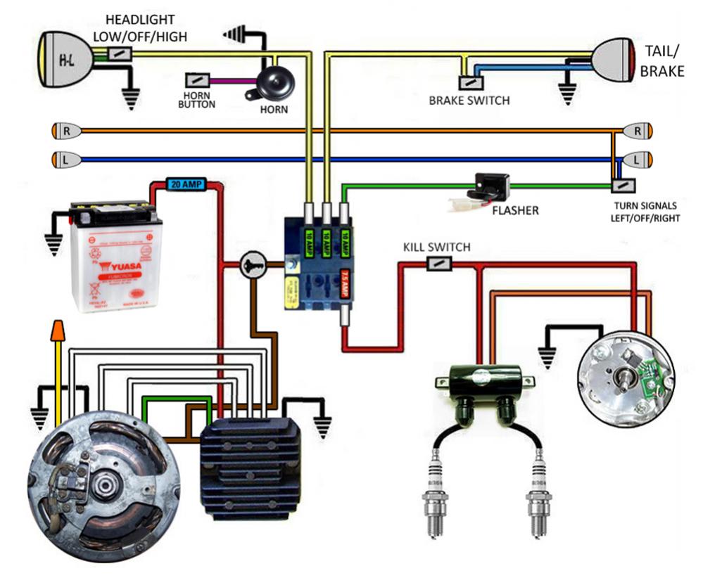
5 Wire Regulator Rectifier Wiring Diagram
Alright, let's dive into the world of 5-wire regulator rectifiers. If you're tinkering with your motorcycle, ATV, scooter, or even a small engine project, understanding this component and its wiring is crucial. Whether you're diagnosing charging issues, performing an upgrade, or simply want a deeper understanding of your vehicle's electrical system, this guide will walk you through the 5-wire regulator rectifier wiring diagram.
Why This Diagram Matters
Why bother learning about a 5-wire regulator rectifier? Simple: it's at the heart of your vehicle's charging system. If your battery isn't holding a charge, your lights are dimming, or your electrical accessories are acting up, the regulator rectifier is often a prime suspect. Knowing how to interpret the wiring diagram allows you to:
- Diagnose charging system problems quickly and accurately.
- Perform repairs and replacements yourself, saving money on labor costs.
- Upgrade your charging system for increased power demands (e.g., adding aftermarket lights).
- Understand the fundamental principles of electrical regulation and rectification.
Key Specs and Main Parts
Before we delve into the diagram itself, let's cover some key components and specifications. The regulator rectifier's job is twofold:
- Rectification: Converting the AC (Alternating Current) output from the stator (or alternator) into DC (Direct Current). Your vehicle runs on DC electricity, but the stator generates AC.
- Regulation: Maintaining a consistent voltage (typically around 13.5-14.5 volts) to charge the battery and power electrical components without overcharging or damaging them.
Here are the key parts usually involved in 5-wire regulator rectifier systems:
- Stator/Alternator: Generates the AC voltage. In many small engine applications, it's often called a magneto.
- Regulator Rectifier: The focus of this article. It takes the AC from the stator and outputs DC to charge the battery and run the electrical system.
- Battery: Stores electrical energy and provides a stable voltage source.
- Wiring Harness: Connects all the electrical components.
- Fuses: Protects the circuit from overcurrent.
Key Specs to Consider:
- Voltage Rating: Typically 12V or 24V, matching your vehicle's electrical system.
- Current Rating: How much current the regulator rectifier can handle. Crucial if you're upgrading your electrical system.
- Number of Phases: Some systems are single-phase, others are three-phase. The 5-wire setup is commonly used for single-phase systems, but variations exist.
Decoding the Diagram: Symbols, Lines, and Colors
A wiring diagram might look intimidating at first, but it's simply a roadmap of the electrical system. Here's how to decipher the key elements:
- Lines: Represent wires. Thicker lines often indicate wires carrying higher current.
- Colors: Each wire is typically color-coded. Common colors include:
- Red: Positive (+) DC power from the battery or regulator rectifier.
- Black: Ground (-) or negative terminal.
- Yellow/White: AC input from the stator.
- Green: Often used as a ground.
- Brown/Blue: Switched power (controlled by the ignition switch).
- Symbols: Represent electrical components:
- Rectifier Diode: A triangle pointing towards a line. Shows the direction of current flow.
- Regulator: A box with symbols representing electronic components.
- Battery: A series of long and short parallel lines.
- Fuse: A squiggly line inside a rectangle.
- Switch: A break in a line that can be opened or closed.
- Ground: Series of descending lines connected to a point.
Now, let's consider the specific connections in a 5-wire regulator rectifier setup. A typical configuration includes:
- Two Yellow/White wires: AC input from the stator. These wires are usually interchangeable. The AC voltage from the stator enters the rectifier here.
- Red wire: DC output to the battery positive terminal and the vehicle's electrical system. This is the regulated DC voltage.
- Green/Black wire: Ground connection to the vehicle's frame or chassis. This completes the circuit.
- Brown/Blue wire: Switched power (typically connects to the ignition switch). This wire may provide power to turn on the regulator or provide a feedback signal.
How It Works: From AC to Smooth DC
Let's break down the process. The stator generates AC voltage when the engine is running. This AC voltage is fed into the regulator rectifier through the two yellow/white wires. Inside the regulator rectifier, the following happens:
- Rectification: Diodes convert the AC voltage into pulsating DC voltage. Diodes act like one-way valves for electricity.
- Regulation: A voltage regulator circuit controls the output voltage to maintain a constant level, preventing overcharging of the battery. This circuit typically uses transistors and other electronic components to regulate the voltage.
- Output: The regulated DC voltage is then outputted through the red wire to charge the battery and power the vehicle's electrical system.
- Ground: The green/black wire provides a return path for the current, completing the circuit.
The brown/blue wire, if present, often serves as a signal wire. It can be used to turn the regulator on and off with the ignition switch or provide feedback to the regulator regarding the system voltage.
Real-World Use: Basic Troubleshooting Tips
Suspect a problem with your regulator rectifier? Here's some basic troubleshooting you can do:
- Visual Inspection: Check for burnt wires, melted connectors, or physical damage to the regulator rectifier.
- Voltage Test: With the engine running, measure the voltage at the battery terminals. It should be between 13.5V and 14.5V. If it's significantly lower or higher, the regulator rectifier might be faulty. A multimeter is essential for this.
- AC Voltage Test (Stator Output): Disconnect the yellow/white wires from the regulator rectifier and measure the AC voltage between them while the engine is running at a moderate RPM. Compare the reading to the manufacturer's specifications. Low or no AC voltage indicates a problem with the stator.
- Continuity Test: Check for continuity between the ground wire and the vehicle's frame. Lack of continuity indicates a poor ground connection.
- Component Test: Some advanced multimeters have a diode test function that can be used to test the internal diodes of the rectifier. Consult your multimeter's manual for instructions.
Important Note: Before performing any electrical tests, disconnect the battery's negative terminal to prevent short circuits.
Safety: Handle with Care!
Working with electrical systems can be dangerous. Always follow these safety precautions:
- Disconnect the Battery: As mentioned above, disconnect the battery's negative terminal before working on any electrical components.
- Wear Safety Glasses: Protect your eyes from sparks and debris.
- Use Insulated Tools: Prevent electrical shocks.
- Work in a Well-Ventilated Area: Some electrical components can release harmful fumes when overheated.
- Be Careful with the Stator: The stator can generate high voltage, especially at higher RPMs. Avoid touching the stator wires when the engine is running.
The regulator rectifier itself can get hot during operation. Avoid touching it immediately after the engine has been running. Faulty regulator rectifiers can overheat and potentially catch fire. Always replace a damaged regulator rectifier with a properly rated replacement.
Understanding the 5-wire regulator rectifier wiring diagram empowers you to diagnose and repair charging system issues, saving you time and money. By following these guidelines and taking necessary safety precautions, you can confidently tackle electrical projects on your vehicle.
Remember this is general guidance; specific wiring arrangements can vary slightly depending on the vehicle manufacturer and model. Consult your vehicle's service manual for the most accurate wiring diagram.
We have a sample 5-wire regulator rectifier wiring diagram file available for download to help you visualize these concepts. You can download it [Link to Download - Placeholder]. Note: Always verify the diagram against your specific vehicle's documentation.