
5.3 Vacuum Lines Diagram Silverado 1500
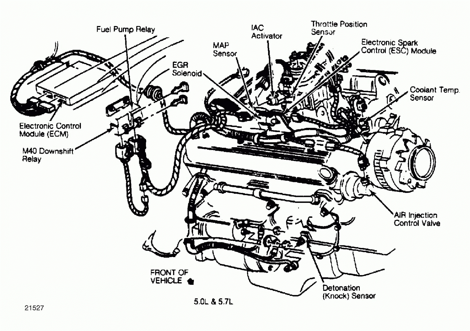
Okay, let's dive into the often-overlooked but absolutely crucial world of vacuum lines in your 5.3L Silverado 1500. This article will break down the vacuum line diagram, explaining its purpose, components, how it functions, and how you can use it for troubleshooting. Having a solid understanding of this system is invaluable for everything from basic maintenance to more complex engine diagnostics.
Purpose of the Vacuum Line Diagram
Why should you even bother understanding the vacuum line diagram? Simple: it's your roadmap to a properly functioning engine. The vacuum system plays a vital role in various engine functions, and a leak or blockage in one of these lines can manifest in a multitude of performance issues. The diagram offers a visual representation of how these components are connected, which helps in:
- Diagnosis and Repair: Identifying vacuum leaks is essential for maintaining optimal engine performance, fuel efficiency, and emissions control. The diagram helps you pinpoint the location of a leak quickly.
- Modification and Upgrades: When adding aftermarket components, understanding the vacuum system is crucial to ensure proper integration. For example, if you're installing a new intake manifold, you need to know where to connect various vacuum-operated accessories.
- General Understanding: Even if you're not planning any major repairs, understanding the system helps you become a more informed vehicle owner.
- Emissions Compliance: Vacuum lines often interface with emissions control devices. Proper function ensures your Silverado meets emission standards.
Key Specs and Main Parts
The 5.3L Vortec engine in your Silverado utilizes vacuum for several critical functions. Here's a breakdown of the key components involved:
- Vacuum Source: The primary vacuum source is the engine's intake manifold. As the pistons move down during the intake stroke, they create a vacuum in the manifold.
- Vacuum Lines: These are typically rubber or plastic hoses that connect the vacuum source to various components. They come in different diameters to accommodate different flow rates.
- Check Valves: These valves allow flow in only one direction, preventing backflow and maintaining vacuum in specific parts of the system.
- Vacuum Reservoir (Canister): This stores vacuum to provide a stable supply for components that require a consistent vacuum source, even when the engine vacuum fluctuates.
- EGR Valve (Exhaust Gas Recirculation): Vacuum is used to control the EGR valve, which recirculates a portion of the exhaust gas back into the intake manifold to reduce NOx emissions.
- PCV Valve (Positive Crankcase Ventilation): The PCV system uses vacuum to draw crankcase fumes into the intake manifold, preventing pressure buildup and reducing emissions.
- Brake Booster: This uses engine vacuum to assist with braking, reducing the effort required to depress the brake pedal.
- HVAC System: Vacuum may be used to control various functions within the heating, ventilation, and air conditioning (HVAC) system, such as mode door actuators.
- Throttle Body: Vacuum can control some functions related to the throttle body itself.
Understanding Symbols in the Vacuum Line Diagram
The vacuum line diagram is like a language, and understanding its symbols is crucial for accurate interpretation. Here's a guide to common symbols:
- Solid Lines: Typically represent vacuum lines. The thickness of the line might indicate the hose diameter, though this is not always consistent.
- Dashed Lines: Often indicate electrical connections or control signals related to vacuum-operated components.
- Arrows: Indicate the direction of airflow or vacuum.
- Circles: May represent vacuum reservoirs or canisters.
- Squares or Rectangles: Often represent vacuum-operated components, such as valves, actuators, or sensors.
- Colors: Different colors may be used to distinguish between different types of vacuum lines or components, but the color coding is not standardized across all diagrams. Always refer to the diagram's legend for clarification.
- Abbreviations: Look out for abbreviations like EGR, PCV, MAP (Manifold Absolute Pressure), and HVAC. These refer to specific components and systems.
Pay special attention to the legend or key that accompanies the diagram. This will explain the meaning of each symbol and color used in that specific diagram. A generic vacuum line diagram is only so helpful. The one specific to your Silverado is the one you want.
How the Vacuum System Works
The vacuum system operates on the principle of pressure differential. The engine creates a vacuum in the intake manifold, which is a lower pressure than the atmospheric pressure outside the engine. This pressure difference is then harnessed to operate various components.
Here's a simplified explanation:
- The engine generates vacuum in the intake manifold.
- Vacuum lines connect the intake manifold to various components, such as the EGR valve, PCV valve, and brake booster.
- The vacuum pulls on diaphragms or pistons within these components, causing them to operate.
- Check valves ensure that vacuum is maintained in specific parts of the system, even when the engine vacuum fluctuates.
- The vacuum reservoir stores vacuum to provide a stable supply for components that require a consistent vacuum source.
Real-World Use: Basic Troubleshooting Tips
A vacuum leak can cause a range of symptoms, including:
- Rough idling
- Poor acceleration
- Reduced fuel economy
- Check engine light (CEL) illuminated with codes related to lean conditions or EGR system malfunctions
- Hissing sound from the engine compartment
Here's how you can use the vacuum line diagram to troubleshoot these issues:
- Visual Inspection: Start by visually inspecting all vacuum lines for cracks, breaks, or loose connections. Pay close attention to areas where the lines are exposed to heat or abrasion.
- Vacuum Gauge Testing: Connect a vacuum gauge to a main vacuum source (like the intake manifold). A low or fluctuating vacuum reading indicates a potential leak.
- Smoke Testing: This is a more advanced technique that involves injecting smoke into the vacuum system and looking for leaks.
- Spray Testing: With the engine running, spray small amounts of carburetor cleaner or starting fluid around vacuum lines and connections. If the engine RPM increases, you've likely found a leak in that area. Use caution with this method as carb cleaner is highly flammable.
- Component Testing: Use the diagram to identify specific components connected to the vacuum system and test their functionality. For example, you can test the EGR valve by applying vacuum to it and observing its response.
Important Note: When replacing vacuum lines, use hoses that are specifically designed for vacuum applications. Fuel lines or other types of hoses are not suitable and may collapse under vacuum.
Safety Considerations
Working on the vacuum system is generally safe, but there are a few precautions to keep in mind:
- Hot Components: Be careful when working around the engine, as some components can get very hot. Allow the engine to cool down before starting any repairs.
- Flammable Liquids: As mentioned earlier, use caution when using carburetor cleaner or starting fluid to locate vacuum leaks. These fluids are highly flammable and can pose a fire hazard. Keep a fire extinguisher nearby.
- Sharp Edges: Some engine components may have sharp edges. Wear gloves to protect your hands.
- Brake Booster: The brake booster stores vacuum. When disconnecting vacuum lines from the booster, be aware that there may be some residual vacuum.
The EGR valve can get very hot after the engine has been running. Exercise extreme caution when working around it to avoid burns.
By carefully inspecting the vacuum lines and using the troubleshooting techniques outlined above, you can often diagnose and repair vacuum leaks yourself, saving time and money. Always consult a professional mechanic if you're unsure about any aspect of the repair process.
We have a high-resolution vacuum line diagram specifically for the 5.3L Silverado 1500 readily available. You can download it and print it out for easy reference while working on your truck. This diagram will be an invaluable tool in your diagnostic and repair efforts, providing a clear visual representation of the entire vacuum system. It will show each line, each component, and how they all interconnect.