
5.3 Vortec Engine Wiring Harness Diagram
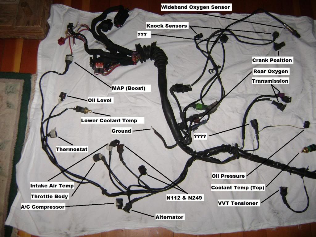
Alright, let's dive deep into the wiring harness diagram for the 5.3 Vortec engine. This isn't just a roadmap; it's the key to understanding how all the electrical components in your engine communicate and function together. Whether you're tackling a repair, swapping an engine, or just expanding your automotive knowledge, grasping this diagram is essential. I have the diagram files, which you can download once you are done reading this article.
Purpose of the 5.3 Vortec Wiring Harness Diagram
Why bother with this diagram? Simple: it's your primary resource for:
- Troubleshooting Electrical Problems: Pinpointing shorts, opens, or faulty sensors. Instead of guessing, you can trace circuits and identify the culprit.
- Engine Swaps: Integrating a 5.3 Vortec into a different vehicle requires understanding how to connect the engine's wiring to the new chassis.
- Repairs: Replacing damaged wiring, connectors, or components becomes much easier when you know exactly what goes where.
- Modification and Upgrades: Adding aftermarket sensors, controllers, or performance enhancements often involves tapping into the existing wiring harness.
- General Understanding: Simply understanding how your engine's electrical system works empowers you to diagnose issues and perform preventative maintenance.
Key Specs and Main Parts of the 5.3 Vortec Wiring Harness
The 5.3 Vortec, a member of the GM LS engine family, came in various configurations across trucks, SUVs, and vans from the late 1990s through the mid-2000s. That means there can be slight variations in the wiring depending on the year, model, and specific options. However, the core components and their wiring remain relatively consistent.
Here's a breakdown of the main parts and their roles:
Core Components
- Engine Control Module (ECM): The brain of the operation. The ECM receives signals from various sensors, processes the data, and controls actuators to optimize engine performance. It controls fuel injection, ignition timing, idle speed, and many other functions.
- Fuel Injectors: Electrically controlled valves that spray fuel into the intake manifold. The ECM controls the duration and timing of the fuel injection pulses.
- Ignition Coils: Generate the high-voltage spark that ignites the air-fuel mixture in the cylinders. Each coil is typically controlled individually by the ECM (coil-on-plug).
- Sensors: Provide the ECM with data about engine operating conditions. Key sensors include:
- Mass Airflow (MAF) Sensor: Measures the amount of air entering the engine.
- Throttle Position Sensor (TPS): Measures the position of the throttle plate.
- Crankshaft Position Sensor (CKP): Monitors the position and speed of the crankshaft.
- Camshaft Position Sensor (CMP): Monitors the position of the camshaft.
- Oxygen (O2) Sensors: Measure the oxygen content in the exhaust gas, providing feedback for fuel trim adjustments.
- Coolant Temperature Sensor (CTS): Measures the temperature of the engine coolant.
- Oil Pressure Sensor: Measures engine oil pressure.
- Actuators: Components that the ECM controls to influence engine operation. Key actuators include:
- Idle Air Control (IAC) Valve (older models): Controls the amount of air bypassing the throttle plate to maintain a stable idle speed. Newer models use electronic throttle bodies.
- Electronic Throttle Body (ETB) (newer models): Controls the throttle plate opening electronically.
- Fuel Pump Relay: Controls the power supply to the fuel pump.
- Cooling Fan Relay: Controls the power supply to the cooling fan(s).
Note: specific components and their locations may vary slightly depending on the exact year and model of your 5.3 Vortec engine.
Understanding Wiring Harness Symbols and Conventions
Wiring diagrams use standardized symbols to represent different components and connections. Here's a breakdown:
- Lines: Represent wires. The thickness of the line doesn't necessarily indicate wire gauge.
- Colors: Each wire is typically identified by a color code (e.g., RED, BLU, GRN/WHT - Green with a White stripe). Refer to a color code chart specific to your vehicle.
- Ground Symbols: Indicate a connection to the vehicle's chassis ground (usually a stylized downward-pointing triangle or a series of horizontal lines).
- Connectors: Represented by various shapes (circles, squares, etc.). They often have numbers or letters indicating the specific pin or terminal within the connector.
- Splices: Represent points where multiple wires are joined together.
- Components: Each component (sensor, relay, etc.) has a specific symbol. You'll need to consult a legend specific to your diagram to identify them all. Relays, for example, are often shown as a coil and a set of contacts.
- Resistors: A zig-zag line.
- Capacitors: Two parallel lines.
- Diodes: A triangle pointing at a vertical line.
Trace the Circuit: The key to understanding the diagram is to trace the flow of electricity through a circuit. Start at the power source (typically the battery or ignition switch), follow the wire through various components, and end at the ground. Pay attention to connectors and splices along the way.
How the 5.3 Vortec Wiring Harness Works
The wiring harness acts as the nervous system of the engine. It provides the pathways for electrical signals to travel between the ECM, sensors, and actuators. Here's a simplified overview:
- Power Distribution: The battery provides the primary source of power. The ignition switch controls power to various circuits when the engine is running. Relays are used to switch high-current circuits (like the fuel pump and cooling fans) using a low-current signal from the ECM.
- Sensor Inputs: Sensors send analog or digital signals to the ECM, providing information about engine conditions. For example, the MAF sensor outputs a voltage signal proportional to the amount of air entering the engine.
- ECM Processing: The ECM analyzes the sensor data using pre-programmed algorithms and lookup tables. It then determines the optimal settings for fuel injection, ignition timing, and other parameters.
- Actuator Control: The ECM sends signals to actuators to control engine operation. For example, it sends pulses to the fuel injectors to inject the correct amount of fuel.
- Feedback Loops: Many systems use feedback loops to ensure accurate control. For example, the O2 sensors provide feedback to the ECM, allowing it to adjust the fuel trim to maintain the ideal air-fuel ratio.
Real-World Use: Basic Troubleshooting Tips
Let's say your engine is misfiring. Here's how the wiring diagram can help:
- Identify the Cylinder: Determine which cylinder is misfiring (using a scan tool or by pulling spark plug wires one at a time).
- Locate the Coil: Find the ignition coil for that cylinder on the wiring diagram.
- Trace the Circuit: Follow the wiring from the coil back to the ECM. Check for any damaged wires, loose connectors, or corroded terminals.
- Test the Coil: Use a multimeter to test the coil's resistance and primary/secondary voltage.
- Check the ECM Signal: Use a test light or oscilloscope to check if the ECM is sending a signal to the coil.
Note: Always disconnect the battery before working on electrical components to prevent shorts and potential damage.
Safety Precautions
Working with automotive electrical systems can be dangerous. Keep these points in mind:
- Disconnect the Battery: Always disconnect the negative battery cable before working on any electrical components.
- High-Voltage Components: Be extremely cautious around ignition coils and spark plug wires. They carry very high voltage and can deliver a painful (and potentially dangerous) shock.
- Airbag Systems: Be aware of the location of airbag modules and follow proper procedures for disabling them before working in their vicinity. Accidental deployment can cause serious injury.
- Fuel System: Exercise caution when working near the fuel system. Fuel is highly flammable.
- Proper Tools: Use the correct tools for the job. Avoid using damaged or makeshift tools.
- Consult a Professional: If you're unsure about any aspect of the repair, consult a qualified mechanic.
The wiring harness diagram is a complex but essential tool for anyone working on a 5.3 Vortec engine. Take the time to understand the symbols, conventions, and circuit layouts. With a little practice, you'll be able to diagnose electrical problems, perform repairs, and even customize your engine with confidence. I have the diagram available for download, so once you're comfortable with these basics, feel free to grab it and start digging deeper into your engine's electrical system!