5.4 Triton 2001 Ford F150 5.4 Engine Diagram
Alright, let's dive into the 5.4 Triton engine found in the 2001 Ford F-150. This engine, while generally reliable, can develop some quirks as it ages. Having a good engine diagram is essential for any serious DIY mechanic, whether you're tackling a simple tune-up or a more complex repair.
Purpose of the Diagram
Why bother with an engine diagram? It's simple: it’s your roadmap to understanding and working on your 5.4 Triton. With a comprehensive diagram, you can:
- Accurately identify engine components. No more guessing which sensor is which!
- Trace circuits and hoses to diagnose electrical or vacuum problems.
- Understand the flow of fluids and gases within the engine.
- Plan repairs more efficiently by visualizing the engine's assembly.
- Order correct parts the first time. Nothing is more frustrating than getting the wrong part and delaying your project.
Whether you’re chasing a misfire, dealing with oil leaks, or just learning about your engine, the diagram will be invaluable. Think of it as the engine's blueprint – essential for effective repairs, modifications, and general maintenance.
Key Specs and Main Parts
The 2001 Ford F-150's 5.4L Triton V8 is a single overhead cam (SOHC) engine. Here's a brief overview of the key specs and main components:
- Displacement: 5.4 liters (330 cubic inches)
- Configuration: V8
- Cylinder Head Design: Single Overhead Cam (SOHC) – This means there's one camshaft per cylinder bank.
- Horsepower: Around 260 hp (depending on specific model year and configuration)
- Torque: Around 350 lb-ft
- Firing Order: 1-3-7-2-6-5-4-8
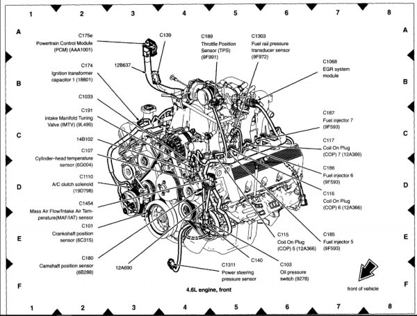
Here's a breakdown of some of the main parts you'll find on the diagram:
- Cylinder Head(s): The top portion of the engine, containing the valves, camshaft, and spark plugs.
- Cylinder Block: The main structure of the engine, containing the cylinders and crankshaft.
- Pistons: Move up and down within the cylinders to compress air and fuel.
- Connecting Rods: Connect the pistons to the crankshaft.
- Crankshaft: Converts the linear motion of the pistons into rotational motion.
- Camshaft: Controls the opening and closing of the valves.
- Intake Manifold: Distributes air to the cylinders.
- Exhaust Manifold: Collects exhaust gases from the cylinders.
- Fuel Injectors: Spray fuel into the intake manifold or directly into the cylinders.
- Throttle Body: Controls the amount of air entering the engine.
- Sensors: Various sensors monitor engine parameters, such as temperature, pressure, and airflow (e.g., Mass Air Flow (MAF) sensor, Engine Coolant Temperature (ECT) sensor, Oxygen (O2) sensors).
- Ignition Coils: Provide the high voltage needed to ignite the air-fuel mixture in the cylinders. The 5.4L Triton uses a Coil-On-Plug (COP) system.
- Water Pump: Circulates coolant through the engine to prevent overheating.
- Oil Pump: Circulates oil through the engine to lubricate moving parts.
- EGR Valve (Exhaust Gas Recirculation): Recirculates a portion of the exhaust gas back into the intake manifold to reduce emissions.
Understanding the Symbols
Engine diagrams aren't just pictures; they use symbols to represent different components and their connections. Here's what to look for:
- Lines: Different types of lines represent different things.
- Solid Lines: Usually indicate fuel lines or vacuum lines.
- Dashed Lines: Often represent electrical wiring. The thickness can sometimes indicate wire gauge.
- Dotted Lines: May indicate diagnostic connections or reference points.
- Colors: Wiring diagrams often use colors to differentiate circuits. The diagram key will specify which color corresponds to which circuit (e.g., Red = Battery Power, Black = Ground).
- Icons: These represent specific components.
- Squares/Rectangles: Can represent relays, sensors, or control modules (like the PCM – Powertrain Control Module).
- Circles: Often represent gauges or switches.
- Resistors: Represented by a zigzag line.
- Capacitors: Represented by two parallel lines.
- Ground: Represented by a series of decreasing horizontal lines.
Always refer to the diagram's legend or key! This is crucial for understanding the specific symbols used in that particular diagram. Manufacturers don't always use the exact same conventions.
How It Works: A Simplified Overview
The 5.4L Triton is a four-stroke engine. That means each piston completes four distinct strokes to complete one combustion cycle:
- Intake: The piston moves down, drawing a mixture of air and fuel into the cylinder.
- Compression: The piston moves up, compressing the air-fuel mixture.
- Combustion (Power): The spark plug ignites the compressed air-fuel mixture, forcing the piston down.
- Exhaust: The piston moves up, pushing the exhaust gases out of the cylinder.
The PCM (Powertrain Control Module), also known as the engine computer, controls various engine functions, including fuel injection, ignition timing, and emissions control. It uses data from the engine sensors to make adjustments and optimize engine performance.
Real-World Use: Basic Troubleshooting Tips
Here are a few scenarios where your engine diagram can come in handy:
- Misfire: If you're experiencing a misfire, the diagram can help you locate the ignition coil, fuel injector, and spark plug for that cylinder. You can then test these components to determine the cause of the misfire.
- Vacuum Leak: Vacuum leaks can cause rough idling and poor performance. Use the diagram to trace vacuum lines and identify potential leak points. Check for cracked or broken hoses.
- Sensor Failure: If a sensor fails, the diagram will show you its location and wiring. You can then test the sensor's voltage or resistance to see if it's functioning correctly. Use a multimeter to perform these tests.
- Overheating: Consult the diagram to trace the coolant flow through the engine, radiator, and water pump. This can help you identify potential blockages or problems with the cooling system.
Example: Let's say you're getting a code for a faulty MAF (Mass Air Flow) sensor. The diagram will show you its exact location in the intake system. You can then disconnect the sensor and use a multimeter to check its wiring and voltage readings, as specified in the repair manual. This will help you determine if the sensor is bad or if the problem lies in the wiring harness.
Safety First!
Working on your engine can be dangerous if you're not careful. Here are a few safety precautions to keep in mind:
- Disconnect the Battery: Always disconnect the negative battery terminal before working on any electrical components. This will prevent accidental shorts and shocks.
- Fuel System: The fuel system is under pressure. Relieve the pressure before disconnecting any fuel lines. Be aware of fuel spills – gasoline is flammable!
- Cooling System: Never remove the radiator cap when the engine is hot. The cooling system is under pressure, and hot coolant can spray out, causing severe burns.
- Electrical Components: Be cautious when working with electrical components. High voltage can be dangerous. Always use insulated tools.
- Moving Parts: Keep your hands and clothing away from moving parts, such as the belts and pulleys.
- Hot Surfaces: Be careful of hot surfaces, such as the exhaust manifold. Allow the engine to cool down before working on it.
High-pressure fuel lines and ignition coils are particularly risky. Always handle them with care and follow the manufacturer's instructions.
Remember: If you're not comfortable performing a particular repair, it's always best to consult a qualified mechanic.
We have a detailed engine diagram available for download. This diagram will provide you with all the information you need to confidently tackle your 5.4L Triton engine. Click the link below to access it.
Please note: This article provides general information only and should not be considered a substitute for professional advice. Always consult the repair manual and follow proper safety procedures when working on your vehicle.