
5.4 Triton Ford F150 Coil Pack Diagram
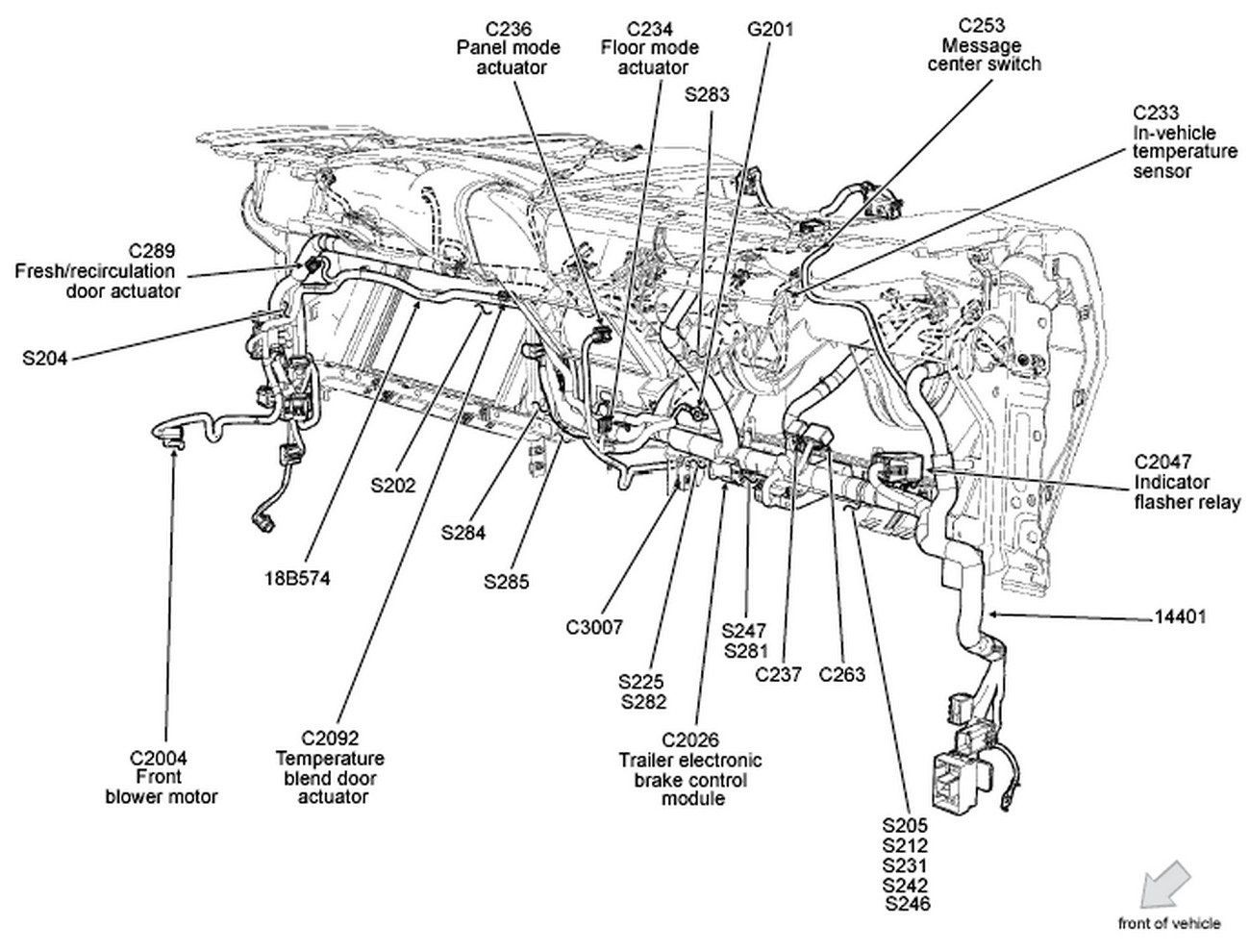
Hey there, gearheads! Let's dive deep into the ignition system of your trusty 5.4 Triton Ford F150. Specifically, we're talking about the coil pack diagram – a crucial resource for anyone tackling engine maintenance, troubleshooting ignition problems, or even performance upgrades. This isn't just a pretty picture; it's a roadmap to understanding how your engine's spark is delivered.
Why Bother with a Coil Pack Diagram?
Let's be honest, staring at a tangle of wires and coils without a clue where they go is a recipe for frustration. The coil pack diagram provides clarity. It's your go-to guide for:
- Diagnostics: Pinpointing misfires, identifying faulty coils, and tracing wiring issues.
- Repairs: Replacing worn-out coils, connectors, or damaged wiring harnesses.
- Upgrades: Installing performance coil packs or aftermarket ignition systems.
- Understanding: Gaining a deeper knowledge of your engine's ignition system and how it functions.
Having a reliable diagram at your fingertips saves time, money, and a whole lot of headaches. Think of it as the Rosetta Stone for your ignition system.
Key Specs and Main Parts of the 5.4 Triton Ignition System
The 5.4 Triton engine utilizes a coil-on-plug (COP) ignition system. This means each cylinder has its own dedicated coil pack, eliminating the need for a distributor. Here’s a breakdown of the key components:
- Coil Packs (Ignition Coils): These are the heart of the system. Each coil is responsible for generating the high-voltage spark needed to ignite the air-fuel mixture in its respective cylinder. The 5.4 Triton typically uses eight individual coils, one for each cylinder.
- Connectors: Each coil pack has a connector that provides it with power and a signal from the powertrain control module (PCM). These connectors are prone to corrosion and damage.
- Wiring Harness: This network of wires connects the coil packs to the PCM and the vehicle's power supply. Look for signs of fraying, cracking, or melting.
- Powertrain Control Module (PCM): This is the engine's brain. It controls the timing and duration of the spark delivered by each coil pack. The PCM uses sensors (crankshaft position sensor, camshaft position sensor, etc.) to determine when to fire each coil.
- Spark Plugs: Located inside each cylinder, spark plugs create the actual spark to ignite the fuel-air mixture. They're consumable and need periodic replacement.
The typical coil pack for a 5.4 Triton will have three pins or terminals. These are usually:
- Power (typically 12V): This supplies the coil with the necessary voltage to operate.
- Ground: Provides a return path for the electrical current.
- Control Signal (from PCM): The PCM sends a signal to the coil to trigger the spark.
Decoding the Diagram: Symbols, Lines, and Colors
A good coil pack diagram is more than just a picture; it's a standardized representation of the electrical circuit. Here's a breakdown of what the symbols and lines typically represent:
- Solid Lines: These represent wires connecting the various components. The thickness of the line might indicate the wire gauge (thicker lines usually indicate wires carrying higher current).
- Dashed Lines: These might represent shielding or grounding connections.
- Coil Symbol (often a looped wire): Represents the ignition coil itself.
- Connector Symbols: These will vary but usually look like a rectangle with pins or sockets. The diagram will often label the connector with a number (e.g., C123) for easy identification.
- Ground Symbol (usually three horizontal lines stacked on top of each other): Indicates a connection to the vehicle's chassis ground.
- Color Coding: This is crucial! Wires are often color-coded, and the diagram will provide a key indicating which color corresponds to which function (e.g., Red = Power, Black = Ground, etc.). Always double-check the color codes against the actual wires in your vehicle.
Important: Ford diagrams can vary slightly depending on the year and trim level of your F150. Always use a diagram specifically for your vehicle!
How It Works: The Ignition Sequence
Here's a simplified overview of how the coil-on-plug ignition system works:
- The crankshaft position sensor (CKP) and camshaft position sensor (CMP) send signals to the PCM, indicating the position of the crankshaft and camshaft.
- The PCM uses this information to determine when each cylinder needs to fire.
- The PCM sends a low-voltage control signal to the appropriate coil pack.
- The coil pack receives the control signal and rapidly charges its internal windings.
- The PCM then cuts off the control signal, causing the magnetic field in the coil to collapse rapidly.
- This rapid collapse induces a very high voltage (tens of thousands of volts) in the coil's secondary winding.
- This high voltage is then discharged through the spark plug, creating a spark that ignites the air-fuel mixture in the cylinder.
This entire process happens in milliseconds, precisely timed by the PCM for optimal engine performance.
Real-World Use: Troubleshooting Tips
Here are some common issues and how the coil pack diagram can help:
- Misfires: If you're experiencing a misfire (rough idling, lack of power, Check Engine Light), the diagram can help you identify which coil pack is associated with the affected cylinder. You can then test the coil pack using a multimeter to check for proper resistance or swap it with a known good coil to see if the misfire moves.
- No Spark: If you're not getting any spark from a particular coil pack, use the diagram to trace the wiring back to the PCM, checking for breaks, shorts, or loose connections. Verify that the coil is receiving power and a control signal from the PCM.
- Wiring Issues: Damaged or corroded wiring can cause all sorts of problems. The diagram allows you to visually inspect the wiring harness and identify any potential issues.
Testing Coil Packs: You can use a multimeter to test the primary and secondary resistance of the coil pack. Compare your readings to the manufacturer's specifications to determine if the coil is faulty. You can also use a spark tester to visually confirm that the coil is producing a spark.
Important Note: A misfire can also be caused by other factors, such as faulty spark plugs, fuel injectors, vacuum leaks, or engine mechanical issues. A coil pack diagram is just one piece of the puzzle.
Safety First! Highlighting Risky Components
Working with electrical systems involves inherent risks. Always observe the following safety precautions:
- Disconnect the Battery: Before working on any electrical components, disconnect the negative battery cable to prevent accidental shocks or short circuits.
- High Voltage: The ignition system generates very high voltage. Never touch the spark plugs or coil packs while the engine is running or the ignition is on.
- Use Proper Tools: Use insulated tools to prevent electrical shocks.
- Work in a Well-Ventilated Area: When working with fuels or solvents, work in a well-ventilated area to avoid inhaling harmful fumes.
Warning: The PCM is a sensitive electronic component. Avoid static electricity discharge when handling it. Ground yourself before touching the PCM or any of its connectors.
Download Your 5.4 Triton Coil Pack Diagram
We've got a detailed coil pack diagram for your 5.4 Triton F150 ready for you to download. This diagram will provide you with the specific wiring configurations and connector locations for your vehicle. Having this resource on hand will make troubleshooting and repairs much easier.
Keep in mind that information provided should be used by skilled people and that safety must always be paramount.