
5.7 Vacuum Line Diagram For Chevy 350
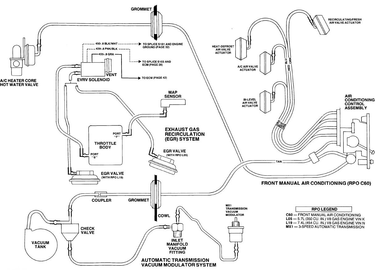
The vacuum system on a classic Chevy 350 small-block engine, specifically the 5.7-liter version, is a critical network of hoses and components responsible for controlling a variety of engine functions. Understanding its intricacies through the vacuum line diagram is crucial for proper diagnosis, maintenance, and even performance modifications. This article will serve as your guide to decoding the 5.7 Chevy 350 vacuum line diagram, empowering you to troubleshoot issues and keep your engine running smoothly.
Purpose of Understanding the Vacuum Line Diagram
Why bother with a vacuum line diagram? Several reasons make it an invaluable tool:
- Troubleshooting Engine Issues: Vacuum leaks are a common cause of poor engine performance, including rough idling, hesitation, reduced fuel economy, and even stalling. A diagram helps you trace lines and identify potential leak locations.
- Ensuring Proper Emissions Control: The vacuum system plays a vital role in emissions control by managing components like the EGR valve and PCV system. A correctly configured system is essential for passing emissions tests.
- Performing Engine Modifications: Whether you're swapping carburetors, installing a performance intake, or upgrading other components, understanding the vacuum system is crucial for ensuring proper operation and avoiding unforeseen problems.
- Restoring or Maintaining a Classic: For those restoring classic vehicles, a vacuum line diagram is essential for accurately routing lines to their original positions, preserving the vehicle's authenticity and functionality.
- Deepening Your Automotive Knowledge: Comprehending how the vacuum system operates provides a deeper understanding of engine management principles, enhancing your overall automotive expertise.
Key Specs and Main Parts
Before diving into the diagram, let's identify the key components and their functions:
- Vacuum Source: The primary vacuum source is the engine intake manifold. The descending pistons create a low-pressure (vacuum) area in the intake, which is then tapped via ports.
- Carburetor: If equipped, the carburetor utilizes vacuum for various functions, including choke pull-off, distributor advance, and idle mixture control.
- Distributor: Vacuum advance mechanisms use vacuum to advance or retard the ignition timing based on engine load. This improves fuel economy and performance.
- PCV Valve (Positive Crankcase Ventilation): This valve regulates the flow of crankcase gases back into the intake manifold for combustion, reducing emissions and preventing pressure buildup.
- EGR Valve (Exhaust Gas Recirculation): The EGR valve reduces NOx emissions by recirculating a portion of the exhaust gas back into the intake manifold.
- Charcoal Canister: This canister stores fuel vapors from the fuel tank to prevent them from escaping into the atmosphere. Vacuum lines connect the canister to the engine, allowing it to purge the vapors into the intake for combustion.
- Vacuum Reservoir (or Can): Some vehicles use a vacuum reservoir to store vacuum for components that require a consistent vacuum supply, even under heavy engine load.
- Vacuum Modulators (Automatic Transmissions): In older automatic transmissions, vacuum modulators control shift timing and firmness based on engine load.
- Vacuum Actuators: These actuators use vacuum to operate various components, such as heater doors, ventilation controls, and cruise control systems.
- Check Valves: These one-way valves prevent vacuum from bleeding off in certain systems, ensuring proper operation.
- Vacuum Hoses: These rubber or plastic hoses connect all the components and carry the vacuum signal.
Understanding the Symbols and Colors
Vacuum line diagrams use a variety of symbols and colors to represent different components and vacuum lines. Common symbols include:
- Solid Lines: Typically represent direct vacuum lines.
- Dashed Lines: Often indicate ported vacuum lines (vacuum available only above idle) or control lines.
- Lines with Arrows: Show the direction of vacuum flow.
- T-Connectors: Indicate where vacuum lines split to supply multiple components.
- Check Valves: Represented by a symbol that looks like a triangle pointing towards a line, indicating the direction of allowed flow.
- Vacuum Reservoirs: Represented by a cylindrical shape.
- Carburetor Vacuum Ports: Often labeled with abbreviations (e.g., "M" for manifold vacuum, "S" for spark vacuum).
Color coding varies depending on the diagram source, but some common color conventions include:
- Black: Often indicates manifold vacuum.
- Green: May represent distributor vacuum advance.
- Red: Could indicate a ported vacuum source.
- Yellow: Might be used for EGR control.
Important: Always refer to the specific vacuum line diagram for your vehicle's year and model to understand the exact meaning of each symbol and color.
How It Works: A Simplified Explanation
The basic principle is simple: the engine creates a vacuum in the intake manifold. This vacuum is then distributed through a network of hoses to various components, which use the vacuum to perform their functions. For example:
- The distributor's vacuum advance unit uses manifold vacuum to advance the ignition timing at idle and light throttle, improving fuel economy.
- The PCV valve uses manifold vacuum to draw crankcase gases into the intake manifold for combustion, reducing emissions.
- The EGR valve uses vacuum to open and allow exhaust gas to recirculate into the intake manifold under certain conditions, reducing NOx emissions.
- The charcoal canister uses vacuum to purge stored fuel vapors into the intake manifold, preventing them from escaping into the atmosphere.
The complexity arises from the various control mechanisms and valves that regulate the vacuum flow to each component based on engine operating conditions. A poorly routed, disconnected or leaking vacuum line disrupts this precisely engineered system leading to various engine malfunctions.
Real-World Use: Basic Troubleshooting Tips
Here's how you can use a vacuum line diagram for troubleshooting:
- Identify the Symptom: What's the problem you're experiencing (e.g., rough idle, poor fuel economy, stalling)?
- Consult the Diagram: Locate the vacuum lines related to the affected component.
- Visually Inspect the Lines: Check for cracks, leaks, disconnections, and proper routing. Pay close attention to areas near heat sources or moving parts.
- Use a Vacuum Gauge: A vacuum gauge can help you measure the vacuum at various points in the system, identifying leaks or restrictions. A steady reading at idle indicates a healthy vacuum system. A fluctuating reading suggests a problem.
- Use a Vacuum Pump: A hand-held vacuum pump allows you to isolate and test individual components, such as the EGR valve or distributor advance unit.
- Listen for Hissing Sounds: A hissing sound often indicates a vacuum leak. Use a length of hose as a stethoscope to pinpoint the source.
- Spray Carb Cleaner or Starting Fluid: Carefully spray small amounts of carb cleaner or starting fluid around vacuum lines and connections. If the engine speed changes, you've likely found a vacuum leak. Caution: Use this method sparingly and avoid spraying near hot surfaces or ignition components to prevent fire hazards.
Safety Considerations
Working on the vacuum system generally doesn't involve high voltage or moving parts, but there are still safety precautions to consider:
- Hot Surfaces: Be cautious of hot engine components, such as the exhaust manifold and engine block. Allow the engine to cool before working on the vacuum system.
- Flammable Liquids: When using carb cleaner or starting fluid to locate vacuum leaks, exercise extreme caution. Avoid spraying near hot surfaces or ignition components to prevent fire hazards. Keep a fire extinguisher nearby.
- Sharp Edges: Be careful of sharp edges on engine components and vacuum line fittings. Wear gloves to protect your hands.
- Eye Protection: Wear safety glasses to protect your eyes from debris.
- Proper Ventilation: Work in a well-ventilated area to avoid breathing in fumes from carb cleaner or other chemicals.
One area that requires caution, especially when dealing with older vehicles, is the fuel vapor canister system. Older canisters can contain a buildup of flammable fuel vapors. Avoid open flames or sparks when working near the canister.
By understanding the vacuum line diagram for your 5.7 Chevy 350 and following these troubleshooting tips, you can diagnose and repair vacuum-related issues, ensuring that your engine runs smoothly and efficiently.
We have a detailed vacuum line diagram available for download. This diagram covers the specific configurations for many 5.7 Chevy 350 models. Click here to download the diagram and take your troubleshooting to the next level!