5.9 Cummins Fuel Shut Off Solenoid Wiring Diagram
If you're wrestling with a 5.9 Cummins that won't start, stalls unexpectedly, or just isn't running right, chances are the Fuel Shut Off Solenoid (FSOS) circuit is to blame. This article will dissect the wiring diagram for the FSOS on a 5.9 Cummins diesel engine, providing you with the knowledge to diagnose and potentially repair issues in this crucial system. Whether you're a seasoned DIY mechanic or just getting started, understanding this diagram is essential for keeping your Cummins running strong. We'll go over the purpose, main parts, how the system works, real-world troubleshooting, and essential safety tips.
Purpose of the Fuel Shut Off Solenoid Wiring Diagram
Why bother understanding this diagram? Several key reasons come to mind:
- Troubleshooting Starting and Stalling Issues: The FSOS is directly responsible for controlling fuel flow to the injection pump. If it's not functioning correctly due to electrical problems, your engine won't start or may stall.
- Performing Repairs: Knowing the wiring allows you to isolate faults within the FSOS circuit, whether it's a broken wire, a faulty connector, or a bad solenoid itself.
- Understanding Engine Operation: Delving into the FSOS circuit gives you a deeper understanding of how the Cummins engine management system works.
- Modifications and Upgrades: If you plan to modify your Cummins, particularly regarding the fuel system or electrical components, understanding the FSOS circuit is crucial for safe and effective modifications.
Key Specs and Main Parts of the FSOS Circuit
Let's break down the key components and specifications you'll encounter when working with the 5.9 Cummins FSOS circuit:
- Fuel Shut Off Solenoid (FSOS): This is the heart of the system. It's an electromechanical device that, when energized, pulls back a lever to allow fuel to flow to the injection pump. When de-energized, it blocks fuel flow, shutting down the engine.
- Injection Pump: Specifically, the fuel injection pump relies on the FSOS to enable or disable fuel flow. Early 5.9 Cummins engines used a Bosch VE rotary pump, while later models used the P7100 inline pump (often referred to as the "P-pump"). While the pump type varies, the FSOS function remains similar.
- Ignition Switch: This is the starting point for the FSOS circuit. When the ignition switch is turned to the "run" position, it sends power to the FSOS relay or directly to the solenoid (depending on the model year).
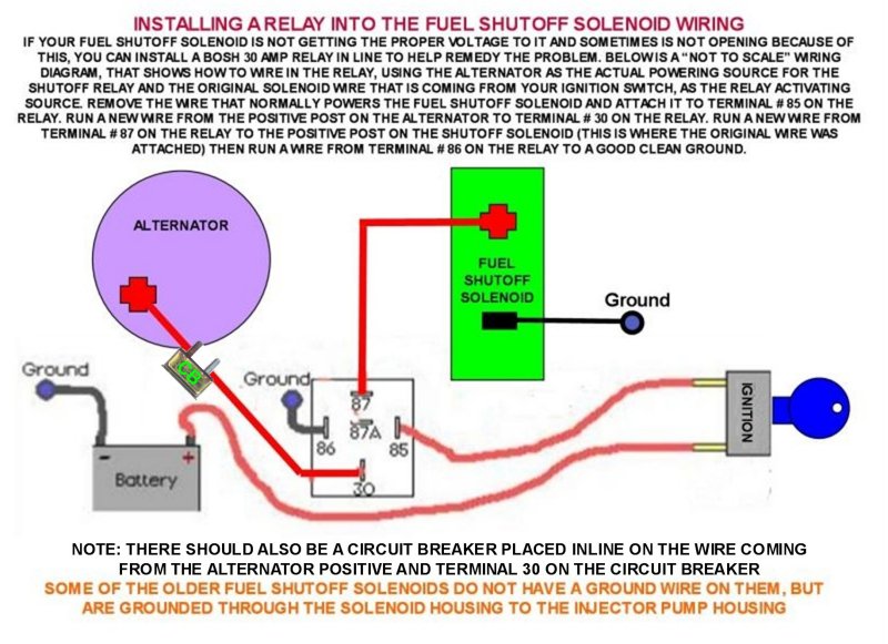
- Relays (if applicable): Some 5.9 Cummins models utilize a relay to provide a higher current path to the FSOS, especially in older models. This relay is triggered by the ignition switch and supplies power to the solenoid.
- Fuses: A fuse protects the FSOS circuit from overcurrent conditions. Typically, this will be a 10-amp or 15-amp fuse located in the fuse box.
- Wiring Harness: The wiring harness connects all the components in the circuit. This harness can be prone to damage from heat, vibration, and abrasion.
- Ground Connection: The FSOS requires a good ground connection to function properly. This is typically achieved by bolting the FSOS body directly to the engine block.
Symbols, Lines, Colors, and Icons in the Wiring Diagram
Understanding the symbols used in the wiring diagram is crucial for interpreting it correctly. Here's a breakdown of common symbols:
- Solid Lines: Represent wires. The thickness of the line *doesn't* necessarily indicate wire gauge, so always refer to the legend or wire markings for accurate gauge information.
- Dotted Lines: Often represent ground connections or shielded wiring.
- Color Codes: Each wire is typically assigned a color code (e.g., RED, BLK, GRN, WHT). These colors are usually abbreviated (e.g., R, B, G, W). Consult the diagram legend for specific color codes. It's vital to stick to these codes when troubleshooting or replacing wires.
- Battery Symbol: Represents the vehicle's battery.
- Ground Symbol: Represents a connection to the vehicle's chassis ground. It looks like a downward-pointing triangle, often filled in.
- Fuse Symbol: Represents a fuse. It typically looks like a squiggly line inside a rectangle or a small line broken by a "C" shape.
- Relay Symbol: Represents a relay. It includes a coil symbol (a loop of wire) and a switch symbol (a set of contacts).
- FSOS Symbol: While there isn't a standardized symbol, the diagram will usually label the FSOS clearly. Sometimes it looks like a coil with an arm connected to it.
How It Works: A Step-by-Step Explanation
Here's how the FSOS circuit typically operates:
- Ignition On: When you turn the ignition switch to the "run" position, voltage is supplied to the FSOS circuit.
- Relay Activation (if applicable): If a relay is present, the ignition switch energizes the relay coil.
- Relay Contacts Close (if applicable): The energized relay coil closes the relay contacts, providing a high-current path from the battery to the FSOS.
- FSOS Energized: Voltage flows to the FSOS.
- Solenoid Actuation: The FSOS, being an electromagnet, pulls back the fuel shut-off lever inside the injection pump.
- Fuel Flow Enabled: With the lever pulled back, fuel is allowed to flow to the injectors, and the engine can start and run.
- Ignition Off: When you turn off the ignition, the voltage to the FSOS is cut off.
- Solenoid De-energized: The FSOS releases the fuel shut-off lever.
- Fuel Flow Blocked: The lever blocks the flow of fuel to the injectors, shutting down the engine.
Real-World Use: Basic Troubleshooting Tips
Here are some basic troubleshooting tips you can use with the FSOS wiring diagram:
- Engine Won't Start:
- Check the fuse for the FSOS circuit. A blown fuse is a common culprit.
- Use a multimeter to check for voltage at the FSOS connector when the ignition is in the "run" position. If there's no voltage, trace the wiring back to the ignition switch, relay (if applicable), and fuse.
- Check the ground connection to the FSOS. A poor ground can prevent the solenoid from energizing properly.
- Listen for a "click" sound from the FSOS when the ignition is turned on. If you don't hear a click, the solenoid may be faulty.
- Engine Stalls Unexpectedly:
- This can indicate an intermittent connection in the FSOS circuit. Check for loose connectors, corroded terminals, and damaged wiring. Pay close attention to areas where the wiring harness is exposed to heat or vibration.
- A failing FSOS can also cause intermittent stalling. Consider replacing the solenoid if you suspect it's the problem.
- Check the voltage to the FSOS while the engine is running. A drop in voltage can cause the solenoid to de-energize and stall the engine.
- Use a Multimeter: A multimeter is your best friend for troubleshooting electrical problems. Learn how to use it to check for voltage, continuity, and resistance.
Safety: Highlighting Risky Components
Working on automotive electrical systems involves inherent risks. Here are some safety precautions to keep in mind:
- Disconnect the Battery: Always disconnect the negative battery cable before working on any electrical components. This will prevent accidental shorts and potential electrical shocks.
- Work in a Well-Ventilated Area: Diesel fuel and electrical components can produce fumes. Work in a well-ventilated area to avoid inhaling harmful vapors.
- Wear Safety Glasses: Protect your eyes from debris and potential sparks.
- Be Careful with Fuel Lines: The fuel system is under pressure. Relieve the pressure before disconnecting any fuel lines.
- Use the Right Tools: Use properly insulated tools designed for automotive electrical work.
- Double-Check Your Work: Before reconnecting the battery, double-check all your connections to ensure they are secure and properly insulated.
- Fuel Shut Off Solenoid could be hot Be wary when handling the FSOS because it will get hot during normal engine operations.
Understanding the FSOS wiring diagram is vital for maintaining the reliable operation of your 5.9 Cummins. By understanding the components, how the circuit functions, and following these troubleshooting tips, you'll be well-equipped to tackle common issues and keep your engine running smoothly. Furthermore, with this understanding you can avoid paying premium prices to a mechanic shop to fix something you are able to diagnose yourself.
We have a detailed 5.9 Cummins Fuel Shut Off Solenoid Wiring Diagram file available for download. This diagram provides a clear and comprehensive overview of the entire FSOS circuit, complete with color codes and component locations. Please contact us for access to this invaluable resource.