6 Pin Accelerator Pedal Position Sensor Wiring Diagram
So, you're diving into the world of 6-pin Accelerator Pedal Position (APP) sensors, eh? Smart move. Understanding this component is crucial for troubleshooting driveability issues, modifying throttle response, or even just deepening your automotive knowledge. This article will give you a detailed breakdown of the 6-pin APP sensor wiring diagram, helping you understand its function, diagnose problems, and even perform basic repairs. We'll keep things technical but approachable, like you're right here in the shop with me.
Why Bother Understanding This Diagram?
Let's be honest, most people only think about the APP sensor when something goes wrong. The check engine light illuminates, the car hesitates, or the dreaded "limp mode" kicks in. Knowing how the APP sensor *should* be wired allows you to:
- Diagnose problems efficiently: Instead of blindly replacing parts, you can pinpoint the exact issue using a multimeter and a good wiring diagram.
- Perform repairs correctly: Wiring mistakes can be catastrophic, damaging the ECU (Engine Control Unit) or creating dangerous driving conditions.
- Modify throttle response (safely!): Some enthusiasts modify the APP sensor signal to achieve a more aggressive throttle feel. Understanding the wiring is paramount for doing this without causing harm.
- Expand your automotive knowledge: The APP sensor is a key component in modern electronic throttle control (ETC) systems. Understanding it is a step towards mastering automotive electronics.
Key Specs and Main Parts of a 6-Pin APP Sensor
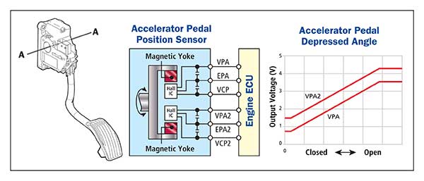
Before we dive into the diagram, let's cover the basics. A 6-pin APP sensor essentially translates the position of your accelerator pedal into an electrical signal that the ECU can understand. The ECU then uses this information to control the throttle plate and ultimately, the engine's power output.
Here's a breakdown of the key specs and components:
- Sensor Type: Typically, these are potentiometer-based or Hall-effect sensors. Potentiometers use a variable resistor, while Hall-effect sensors use magnetic fields to determine pedal position.
- Supply Voltage (Vref): Most APP sensors operate on a 5-volt reference signal provided by the ECU. This reference voltage is crucial for the sensor's operation.
- Signal Output(s): Modern vehicles often use two output signals for redundancy and fault detection. This is why you see multiple sensor signal wires in the diagram.
- Ground: Provides a stable electrical ground for the sensor.
- Connector: The physical connector that plugs into the APP sensor. The pinout of this connector is what the wiring diagram describes.
- Return Signal (Optional): Some advanced systems may have a return signal to better monitor the health of the sensor.
Decoding the Wiring Diagram: Symbols, Lines, and Colors
Now, let's tackle the wiring diagram itself. A typical 6-pin APP sensor wiring diagram will look something like this (remember, variations exist between manufacturers and models, so always consult the specific diagram for your vehicle):
We have a file containing a representative diagram available for download at the end of this article.
Here’s how to interpret the common symbols and conventions:
- Lines: Lines represent wires. The thicker the line, the more important (usually carrying higher current).
- Colors: Wire colors are *crucial*. They indicate the specific function of each wire. Common colors include:
- Red: Typically, the 5V reference voltage (Vref).
- Black: Ground.
- Green/Blue/Yellow: Signal wires. The specific color combination will vary.
- White: Can be various signals or sometimes return signals.
- Icons:
- Connector symbols: Show the physical connector, with pins numbered (1-6 in our case).
- Ground symbol: A symbol that looks like an inverted triangle, connected to ground.
- ECU symbol: Indicates the wire connects to the Engine Control Unit.
- Potentiometer symbol: If the APP sensor uses a potentiometer, you'll see its schematic representation.
- Pin Numbers: Each pin on the connector is numbered, usually 1 through 6. The diagram will tell you what each pin does. For example:
- Pin 1: 5V Reference (Vref)
- Pin 2: Signal 1
- Pin 3: Ground
- Pin 4: Signal 2
- Pin 5: Not Used (NC) or Return Signal
- Pin 6: Signal Ground
Important Note: Never assume wire colors are universal! Always verify the wiring diagram for your specific vehicle model. Using the wrong diagram can lead to misdiagnosis and potential damage.
How It Works: From Pedal to Power
The magic happens like this:
- You press the accelerator pedal.
- The mechanical linkage moves the potentiometer (or affects the Hall-effect sensor).
- The sensor outputs two varying voltage signals, corresponding to the pedal's position. These signals are typically within a range, say, 0.5V to 4.5V.
- The ECU reads these voltage signals. Because there are two signals, the ECU can cross-reference them to ensure accuracy and detect faults. If the signals don't agree within a certain tolerance, a diagnostic trouble code (DTC) is set, and the check engine light comes on.
- The ECU uses the APP sensor data, along with other sensor data (engine speed, mass airflow, etc.), to determine the optimal throttle plate opening.
- The ECU sends a signal to the throttle body to adjust the throttle plate, controlling the amount of air entering the engine.
- More air and fuel equals more power!
Real-World Use: Basic Troubleshooting Tips
Here are some common issues and how to use the wiring diagram for troubleshooting:
- P0121, P0122, P0123, P0220, P0221, P0222, P0223 (APP Sensor Circuit Malfunctions): These codes typically indicate a problem with the APP sensor circuit.
- Check the basics: Is the connector properly seated? Are any wires damaged or corroded?
- Verify Vref: Use a multimeter to check if the 5V reference voltage is present at the appropriate pin (usually Pin 1, but confirm with the diagram). If no voltage, the problem lies with the ECU or the wiring to the ECU.
- Test signal wires: With the ignition on, use a multimeter to measure the voltage on the signal wires (usually Pins 2 and 4). The voltage should change smoothly as you press and release the accelerator pedal. If the voltage is erratic or absent, the sensor is likely faulty. Compare the two signal readings to the specified range for your vehicle. Large discrepancies indicate a sensor problem.
- Check ground: Verify that the ground wire (usually Pin 3) has a good connection to the vehicle's chassis ground.
- Limp Mode: If the ECU detects a major fault with the APP sensor, it may put the vehicle into limp mode to limit engine power and prevent further damage. Troubleshooting as above is crucial.
Safety First: Handle with Care
Working with electrical systems always carries risks. Here are some crucial safety precautions:
- Disconnect the battery: Before working on any electrical component, disconnect the negative terminal of the battery. This will prevent accidental shorts and potential electrocution.
- Use a multimeter safely: Make sure your multimeter is properly calibrated and set to the correct voltage range. Never probe live circuits without proper training.
- Be careful with wiring: Avoid damaging wires or connectors. If you need to cut or splice wires, use proper tools and techniques. Solder and heat shrink tubing are your friends!
- ECU sensitivity: The ECU is a sensitive electronic device. Avoid static electricity and never disconnect or connect the ECU while the ignition is on.
High Risk Components The ECU is the most sensitive and expensive component in this circuit. Incorrect wiring or voltage can easily damage it. Also, working around the engine bay has inherent risks - be mindful of hot surfaces, moving parts, and sharp edges.
With a solid understanding of the 6-pin APP sensor wiring diagram, you'll be well-equipped to diagnose problems, perform repairs, and even explore modifications safely. Remember to always consult the specific wiring diagram for your vehicle and take the necessary safety precautions.
As promised, you can download a representative 6-Pin APP sensor wiring diagram file from the link below:
[Download 6-Pin APP Sensor Wiring Diagram]