6 Pin Throttle Position Sensor Wiring Diagram
Alright, let's dive into the fascinating world of Throttle Position Sensors (TPS) and their wiring diagrams. Knowing how this system works and being able to interpret the wiring is crucial for anyone who's serious about diagnosing and repairing engine performance issues. This isn't just for seasoned mechanics; with a bit of understanding, even experienced DIYers can tackle TPS-related problems. We're going to specifically focus on the 6-pin configuration, which is common in many modern vehicles, but understanding the principles here will translate to other TPS types as well.
Why This Diagram Matters
Why bother learning about TPS wiring diagrams? The answer is simple: accurate diagnosis and repair. Without a solid understanding of the wiring, you're essentially guessing when trying to troubleshoot engine performance issues. This knowledge is invaluable for:
- Troubleshooting: Identifying a faulty TPS, wiring harness damage, or issues with the Engine Control Unit (ECU).
- Repair: Correctly repairing damaged wiring or replacing a faulty TPS.
- Performance Tuning: Ensuring the TPS is calibrated correctly for optimal engine performance after modifications.
- Learning: Gaining a deeper understanding of how your engine management system works.
Key Specs and Main Parts
Before we jump into the diagram itself, let's cover the essential components and specifications associated with a 6-pin TPS.
Main Parts:
- TPS Sensor: The core component that measures the throttle plate's position. This is typically a potentiometer (variable resistor).
- Connector: The electrical connector that physically connects the TPS to the vehicle's wiring harness. This is the part with the six pins we're interested in.
- Wiring Harness: The bundle of wires that connect the TPS to the ECU and other components.
- ECU (Engine Control Unit): The "brain" of the engine management system. It receives the TPS signal and uses it to calculate fuel delivery, ignition timing, and other critical parameters.
Typical Pin Assignments (6-Pin TPS):
While the exact pin assignments can vary slightly depending on the vehicle manufacturer, a common configuration looks something like this:
- VREF (Voltage Reference): A stable 5V (typically) supplied by the ECU. This provides the voltage source for the potentiometer within the TPS.
- Ground (GND): Provides a return path for the electrical current.
- Signal (SIG): The output signal from the TPS that represents the throttle plate angle. This voltage varies proportionally with throttle position.
- TP IDLE (Throttle Position Idle): An input or output used to indicate the throttle is closed.
- TP WOT (Throttle Position Wide Open Throttle): An input or output used to indicate the throttle is fully open.
- Sensor Return (GND): A second ground, often used for improved noise immunity and signal stability.
Important Note: Always consult the specific wiring diagram for your vehicle. Don't assume that the pin assignments are the same across all makes and models. Using the wrong wiring configuration could damage the TPS or the ECU.
Symbols – Understanding the Diagram
Understanding the symbols in a TPS wiring diagram is critical for proper interpretation. Here are some common elements you'll encounter:
- Lines: Represent wires. Solid lines indicate a direct connection, while dashed lines might indicate a shielded wire or a connection that's part of a larger harness.
- Colors: Each wire is typically identified by a color code (e.g., Red, Black, Blue/White). These colors are essential for tracing wires and ensuring you're working with the correct circuit.
- Connectors: Shown as rectangular or circular shapes with numbers indicating pin positions.
- Ground Symbols: Represent electrical ground. Common ground symbols include three horizontal lines decreasing in length.
- Voltage Source Symbols: Indicate the voltage source, often labeled with the voltage value (e.g., 5V).
- TPS Sensor Symbol: A schematic representation of the potentiometer within the TPS.
- ECU Symbol: A rectangular box representing the Engine Control Unit, with numbered pins indicating the connections to the TPS.
- Resistor Symbols: Show resistors and their function in the circuit.
The diagram will also show labels near each wire, indicating the function of that wire (e.g., "VREF," "TPS Signal," "Ground"). Pay close attention to these labels!
How It Works
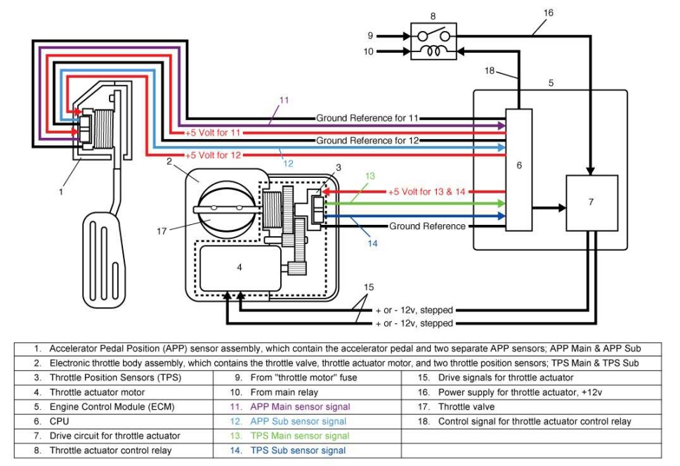
The TPS is essentially a variable resistor, or potentiometer, that changes its resistance based on the position of the throttle plate. The ECU provides a stable voltage reference (VREF), typically 5V, to one side of the potentiometer. The other side is connected to ground. As the throttle plate rotates, the wiper arm of the potentiometer moves, changing the resistance between VREF and the signal (SIG) output. This change in resistance results in a change in voltage on the SIG wire.
The ECU monitors the voltage on the SIG wire. When the throttle is closed, the voltage is typically low (e.g., 0.5V). As the throttle opens, the voltage increases proportionally, reaching a maximum value (e.g., 4.5V) when the throttle is wide open. The ECU uses this voltage signal to determine the throttle position and adjust fuel delivery, ignition timing, and other parameters accordingly.
The TP IDLE and TP WOT signals are often simple on/off switches that provide confirmation to the ECU that the throttle is indeed closed or fully open. These can be used for error checking or for specific engine management strategies.
Real-World Use – Basic Troubleshooting Tips
Here's how you can use your understanding of the TPS wiring diagram to troubleshoot common problems:
- Check for Voltage on VREF: Use a multimeter to verify that the ECU is supplying the correct voltage (typically 5V) to the VREF pin. No voltage here indicates a problem with the ECU or the wiring between the ECU and the TPS.
- Check the Ground Connection: Ensure a good ground connection at the ground pin. A poor ground can cause erratic readings. Use a multimeter to measure the resistance between the ground pin and a known good ground point on the vehicle chassis. It should be close to 0 ohms.
- Monitor the Signal Voltage: With the engine running (or with the ignition on and the engine off), use a multimeter to monitor the voltage on the SIG wire. The voltage should change smoothly and proportionally as you open and close the throttle. Erratic or jumpy voltage readings indicate a faulty TPS.
- Check for Continuity: Use a multimeter to check for continuity in the wiring between the TPS connector and the ECU connector. Broken or damaged wires can cause signal problems.
- Scan for Diagnostic Trouble Codes (DTCs): Use an OBD-II scanner to check for any DTCs related to the TPS. These codes can provide valuable clues about the nature of the problem. Common codes include P0120 (Throttle Position Sensor Circuit Malfunction), P0121 (Throttle Position Sensor Circuit Range/Performance), and P0122 (Throttle Position Sensor Circuit Low Input).
Safety
Working with electrical systems can be dangerous. Here are some safety precautions to keep in mind:
- Disconnect the Battery: Always disconnect the negative battery terminal before working on any electrical components. This will prevent accidental shorts and electrical shocks.
- Be Careful Around High-Voltage Components: Be especially cautious around components such as the ignition coil and fuel injectors, which can carry high voltage.
- Use Proper Tools: Use insulated tools designed for automotive electrical work.
- Don't Work in Wet Conditions: Avoid working on electrical systems in wet or damp environments.
- Consult a Professional: If you're not comfortable working on electrical systems, consult a qualified mechanic. The ECU is a particularly sensitive and expensive component; improper handling or incorrect wiring can cause irreversible damage.
Remember, this article provides general guidance. Always refer to the specific wiring diagram for your vehicle. With a solid understanding of the principles and a careful approach, you can confidently troubleshoot and repair TPS-related problems.
We have a detailed, downloadable 6-pin TPS wiring diagram file available. This resource can be invaluable for your troubleshooting and repair efforts. Please contact us through the contact form if you want access to the file and other information.