6.0 Powerstroke Fuse Panel 2004 Ford F250 Fuse Box Diagram
Alright, let's dive into the often-overlooked but crucial component of your 2004 Ford F-250: the 6.0 Powerstroke fuse panel. Having a solid understanding of its layout and function is invaluable for diagnostics, repairs, modifications, and even just understanding how your truck's electrical system operates. This isn’t just about replacing a blown fuse; it’s about understanding the nervous system of your beast of a truck.
Purpose of the Fuse Box Diagram
Why bother with a fuse box diagram? Simple: it's your roadmap to electrical troubleshooting. Imagine trying to fix a faulty radio without knowing which fuse protects it. You'd be poking around in the dark! The fuse box diagram provides the following key benefits:
- Efficient Troubleshooting: Quickly identify and check fuses related to a specific malfunctioning component. This cuts down diagnostic time significantly.
- Preventing Damage: Replacing a fuse with the wrong amperage rating can lead to component damage or even electrical fires. The diagram ensures you use the correct fuse.
- Safe Modifications: Adding aftermarket accessories requires tapping into the electrical system. Knowing fuse locations and ratings helps you do this safely and correctly.
- General Knowledge: Understanding your truck's electrical architecture empowers you to perform basic maintenance and repairs yourself, saving you money and time.
Key Specs and Main Parts
The 2004 Ford F-250 6.0 Powerstroke actually has two primary fuse boxes: the under-dash (or interior) fuse box and the under-hood (or engine compartment) fuse box. Each serves a distinct purpose, protecting different circuits and components.
Under-Dash Fuse Box
This fuse box is usually located on the driver's side, often tucked away behind a panel or accessible after removing a small trim piece. It primarily protects circuits for interior functions, such as:
- Radio
- Interior lights
- Power windows and locks
- Instrument cluster
- Air conditioning and heating controls
Under-Hood Fuse Box
Located in the engine compartment (usually on the driver's side), this fuse box protects critical engine and drivetrain components, including:
- Fuel pump
- Engine Control Module (ECM) - the brain of the engine
- Glow plug system (crucial for cold starting)
- Transmission control module (TCM)
- Starting system
- Lighting (headlights, taillights)
Key Specs: Fuses are rated in amperes (amps), indicating the amount of electrical current they can handle before blowing. Common ratings include 5A, 7.5A, 10A, 15A, 20A, 25A, 30A, and higher. The diagram will specify the correct amperage for each fuse location. Relays are also housed in these fuse boxes. A relay is an electrically operated switch that allows a low-current circuit to control a high-current circuit. They're used for things like headlights, starter motors, and other high-power components.
Symbols – Interpreting the Diagram
Fuse box diagrams aren’t always intuitive. They use symbols and conventions to convey information efficiently. Here's a breakdown:
- Lines: Lines represent electrical circuits. Thicker lines often indicate higher current capacity.
- Colors: Color coding isn't standardized across all diagrams, but it can indicate the type of circuit (e.g., red for power, black for ground). Always refer to the specific legend on the diagram.
- Icons: These are the most important. Icons represent the components that each fuse protects. Common icons include:
- Lightbulb: Headlights, taillights, interior lights
- Radio: Audio system
- Fan: Blower motor (for heating and air conditioning)
- Battery: Starting system
- Engine: Engine control circuits
- Window: Power windows
- Lock: Power door locks
The diagram will typically have a legend that explains each symbol. Don't assume you know what an icon means – always check the legend!
How It Works
The fuse box acts as a central distribution point for electrical power. Power from the battery is distributed to various circuits through the fuses and relays. Each fuse is a sacrificial element designed to protect a specific circuit. If the current exceeds the fuse's rating (due to a short circuit, overload, or component failure), the fuse's internal element melts, breaking the circuit and preventing damage to the wiring and components. Think of it like a controlled weak point in the electrical system. A blown fuse is a signal that something is wrong, and needs further investigation.
Relays, on the other hand, are used to control high-current circuits with low-current signals. For example, the starter motor requires a significant amount of current. The ignition switch, however, can't handle that much current directly. Instead, the ignition switch activates a relay, which then connects the battery directly to the starter motor.
Real-World Use – Basic Troubleshooting Tips
Here's how to use the fuse box diagram for basic troubleshooting:
- Identify the Problem: What's not working? Be as specific as possible. Is it the driver-side window, the headlights, or something else?
- Locate the Relevant Fuse: Consult the fuse box diagram to find the fuse associated with the malfunctioning component. Double-check that you're looking at the correct diagram for your truck (2004 F-250 6.0 Powerstroke).
- Inspect the Fuse: Remove the fuse using a fuse puller (a small plastic tool designed for this purpose). Examine the fuse element. If it's broken or blackened, the fuse is blown.
- Replace the Fuse: Replace the blown fuse with a new fuse of the exact same amperage rating. Never use a fuse with a higher amperage.
- Test the System: Turn on the ignition and test the component that was malfunctioning. If it now works, you've solved the problem!
- If the Fuse Blows Again: If the new fuse blows immediately or shortly after replacement, there's a more serious problem. This indicates a short circuit or an overload in the circuit. You'll need to investigate further, potentially using a multimeter to check for shorts or consult a qualified mechanic.
Example: Your headlights aren't working. You consult the under-hood fuse box diagram and find the fuse labeled "Headlights." You pull the fuse and see that the element is broken. You replace it with a new fuse of the correct amperage (e.g., 15A). The headlights now work. Problem solved!
Safety – Highlight Risky Components
Working with electrical systems can be dangerous. Always take the following precautions:
- Disconnect the Battery: Before working on any electrical system, disconnect the negative battery terminal. This prevents accidental shorts and potential shocks.
- Use the Right Tools: Use insulated tools designed for electrical work.
- Don't Work in Wet Conditions: Water and electricity don't mix.
- Be Careful with High-Voltage Components: The ignition system and certain sensors operate at high voltage. Avoid touching these components while the engine is running.
- Avoid Tampering with Airbag Circuits: Airbag circuits are extremely sensitive. Incorrect handling can cause accidental deployment, which can be dangerous. If you need to work near airbag components, consult a qualified technician.
- Fuses for the PCM (Powertrain Control Module) and IDM (Injector Driver Module): These are critical for engine operation. Incorrect fuses or faulty wiring here can cause serious engine damage. Exercise extreme caution when working with these circuits.
Important Note: If you're not comfortable working with electrical systems, it's best to consult a qualified mechanic. Electrical problems can be complex and require specialized knowledge and equipment to diagnose and repair safely.
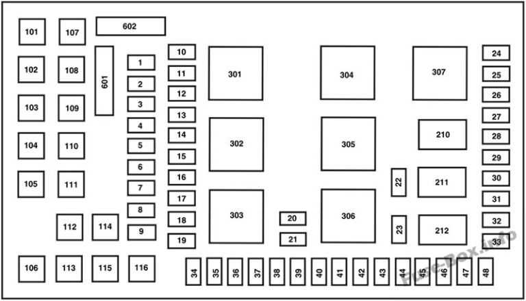
We have a downloadable copy of the 2004 Ford F-250 6.0 Powerstroke fuse box diagram available. This diagram will provide you with the exact locations, amperage ratings, and component designations for both the under-dash and under-hood fuse boxes. Armed with this information, you'll be well-equipped to tackle basic electrical troubleshooting and maintenance on your truck. Download the diagram and keep it handy – you never know when you might need it!