
6.0 Vortec Wiring Harness And Computer
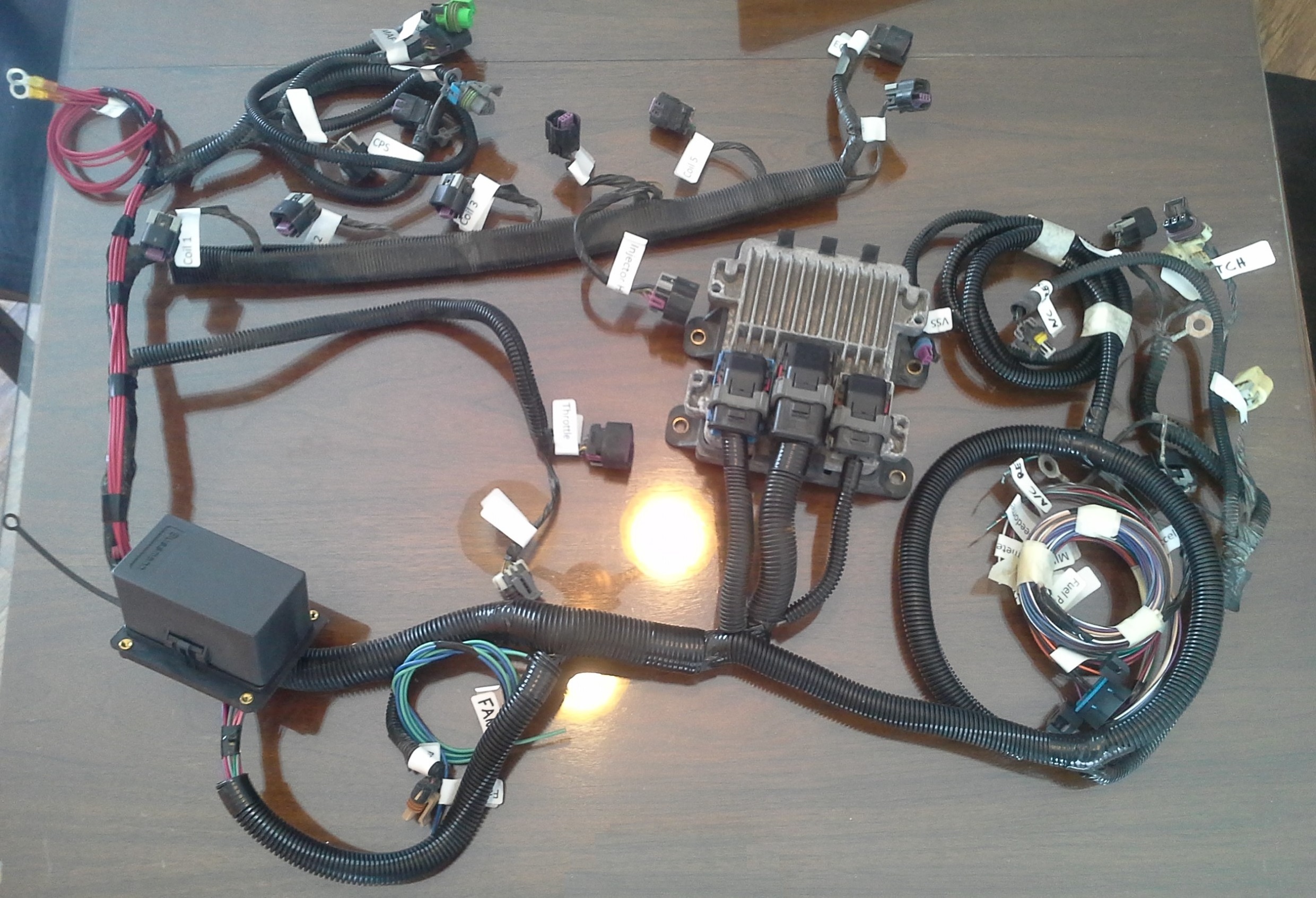
Understanding the wiring harness and computer (Engine Control Module or ECM) of a 6.0 Vortec engine is crucial for various reasons. Whether you're performing routine maintenance, troubleshooting electrical issues, swapping the engine into a different vehicle, or modifying its performance, knowing the ins and outs of this system is essential. This article provides a detailed explanation of the 6.0 Vortec wiring harness and computer, empowering you to tackle repairs, modifications, and diagnostic procedures with confidence.
Purpose and Significance
Why bother learning about the wiring harness and ECM? Several key reasons make this knowledge invaluable:
- Diagnostics and Repair: Pinpointing faulty sensors, actuators, or wiring issues becomes significantly easier with a solid understanding of the system's architecture. You can use a multimeter or scan tool to effectively trace circuits and identify problem areas.
- Engine Swaps: Swapping a 6.0 Vortec into a different vehicle requires careful integration of the engine's wiring harness with the host vehicle's electrical system. This knowledge is critical for a successful and reliable swap.
- Performance Modifications: Tuning the ECM for performance enhancements (e.g., more aggressive timing, adjusted fuel delivery) requires understanding how the ECM controls various engine parameters. You also may need to add or modify wiring to accommodate new sensors or actuators.
- Customization: Tailoring the wiring harness to your specific needs, such as removing unnecessary circuits or adding custom features, requires a thorough understanding of its layout and functionality.
Key Specs and Main Parts
The 6.0 Vortec wiring harness is a complex assembly of wires, connectors, and components designed to transmit signals and power between the ECM and various engine sensors and actuators. The ECM, acting as the engine's brain, processes sensor data and controls actuators to optimize engine performance.
Key Components:
- ECM (Engine Control Module): The central processing unit that controls engine operation. It receives data from sensors, processes it based on pre-programmed calibrations, and controls actuators to achieve optimal performance, fuel economy, and emissions.
- Sensors: These devices monitor various engine parameters and send signals to the ECM. Common sensors include:
- MAP (Manifold Absolute Pressure) Sensor: Measures the pressure inside the intake manifold.
- MAF (Mass Airflow) Sensor: Measures the amount of air entering the engine.
- TPS (Throttle Position Sensor): Indicates the throttle plate's position.
- ECT (Engine Coolant Temperature) Sensor: Measures the coolant temperature.
- O2 Sensors (Oxygen Sensors): Measure the oxygen content in the exhaust gas.
- Crankshaft Position Sensor (CKP): Monitors the crankshaft's position and speed.
- Camshaft Position Sensor (CMP): Monitors the camshaft's position.
- Actuators: These devices are controlled by the ECM to adjust engine parameters. Common actuators include:
- Fuel Injectors: Deliver fuel into the cylinders.
- Ignition Coils: Generate the spark that ignites the air-fuel mixture.
- Idle Air Control (IAC) Valve: Controls the amount of air bypassing the throttle plate during idle. (Note: Some later models use electronic throttle control and eliminate the IAC)
- EVAP (Evaporative Emission Control) System Components: Controls fuel vapor recovery.
- Connectors: Provide secure and reliable connections between the wiring harness and the sensors, actuators, and ECM. They are often color-coded and keyed to prevent misconnection.
- Relays and Fuses: Protect circuits from overloads and provide switching for high-current components.
Key Specifications:
Specific connector pinouts and wire colors vary slightly depending on the model year and application of the 6.0 Vortec. It is critical to consult a wiring diagram specific to your engine's year and service number. General characteristics include:
- Voltage: Primarily 12V DC.
- Wire Gauge: Varies depending on the current carrying capacity required for each circuit. Power and ground wires are typically larger gauge than signal wires.
- ECM Connector Pin Count: Typically in the 80-pin range, split across multiple connectors.
Symbols, Lines, Colors, and Icons
Understanding the symbols, lines, colors, and icons used in a 6.0 Vortec wiring diagram is crucial for interpreting the schematic accurately. Here's a breakdown:
- Lines: Represent wires. Solid lines indicate direct connections, while dashed lines may indicate shielded wires or less critical connections.
- Colors: Each wire is assigned a specific color code. This color code is usually indicated alongside the wire on the diagram. Refer to a color code legend for accurate interpretation. Common colors include:
- Red: Typically indicates a power source (e.g., battery voltage).
- Black: Typically indicates ground.
- Orange: Often used for constant power.
- Pink: Often used for switched power.
- Various other colors: Used for signal wires from sensors and to actuators.
- Symbols:
- Resistors: Represent components that resist the flow of electricity.
- Capacitors: Store electrical energy.
- Diodes: Allow current to flow in only one direction.
- Relays: Electrically operated switches.
- Ground Symbols: Indicate a connection to ground (chassis or engine block).
- Connectors: Represented by various symbols indicating the number of pins and connector type.
- Icons:
- Sensors: May be represented by icons that resemble the sensor type (e.g., a rectangle with an arrow for a MAF sensor).
- Actuators: Similar to sensors, actuators may have icons that represent their function (e.g., a coil for an ignition coil).
How It Works
The 6.0 Vortec engine management system operates on a closed-loop feedback system. Here's a simplified explanation:
- Sensors Collect Data: Sensors like the MAF, MAP, TPS, ECT, and O2 sensors constantly monitor engine conditions and send signals to the ECM.
- ECM Processes Data: The ECM receives these signals and processes them based on pre-programmed calibrations stored in its memory.
- ECM Controls Actuators: Based on the processed data, the ECM controls actuators like the fuel injectors, ignition coils, and IAC valve (if equipped) to achieve the desired engine performance, fuel economy, and emissions.
- Feedback Loop: O2 sensor data provides feedback to the ECM regarding the air-fuel mixture. The ECM adjusts fuel injector pulse width to maintain the optimal air-fuel ratio (typically around 14.7:1, also known as stoichiometric). This continuous feedback loop ensures efficient and clean combustion.
The ECM also monitors various engine parameters for faults. If a fault is detected, the ECM will store a Diagnostic Trouble Code (DTC) and may illuminate the Malfunction Indicator Lamp (MIL), also known as the "check engine light."
Real-World Use: Basic Troubleshooting Tips
Here are some basic troubleshooting tips when working with a 6.0 Vortec wiring harness and ECM:
- Check for DTCs: Use an OBD-II scan tool to retrieve any stored DTCs. These codes can provide valuable clues about the source of the problem.
- Inspect Wiring and Connectors: Carefully inspect the wiring harness and connectors for any signs of damage, corrosion, or loose connections. Pay close attention to areas that are exposed to heat, vibration, or moisture.
- Use a Multimeter: Use a multimeter to check for voltage, continuity, and resistance in various circuits. Refer to the wiring diagram to identify the correct test points.
- Check Fuses and Relays: Ensure that all fuses and relays are in good working order. Replace any blown fuses or faulty relays.
- Isolate the Problem: Try to isolate the problem to a specific circuit or component. For example, if you suspect a faulty sensor, disconnect it and see if the problem goes away.
Safety Considerations
Working with electrical systems can be dangerous. Here are some important safety precautions:
- Disconnect the Battery: Always disconnect the negative battery cable before working on the wiring harness or ECM. This will prevent accidental shorts and electrical shocks.
- Handle the ECM with Care: The ECM contains sensitive electronic components that can be damaged by static electricity. Ground yourself before handling the ECM.
- Avoid Working in Wet Conditions: Never work on the wiring harness or ECM in wet conditions. Water can conduct electricity and create a serious safety hazard.
- Be Aware of High-Voltage Components: The ignition system contains high-voltage components that can deliver a dangerous shock. Avoid touching these components while the engine is running.
- Fuel System Safety: Disconnecting fuel lines or working on fuel injectors requires extreme caution. Relieve fuel pressure before disconnecting any fuel lines. Work in a well-ventilated area and avoid sparks or open flames.
Important: Always consult a qualified mechanic or automotive electrician if you are unsure about any aspect of working with the 6.0 Vortec wiring harness and computer.
We have a detailed wiring diagram file for the 6.0 Vortec that will be a valuable resource in your troubleshooting and repair endeavors. Feel free to reach out, and we'll be happy to provide you with a copy. Remember, accurate information is the cornerstone of successful auto repair.