
7 Blade Trailer Connector Wiring Diagram
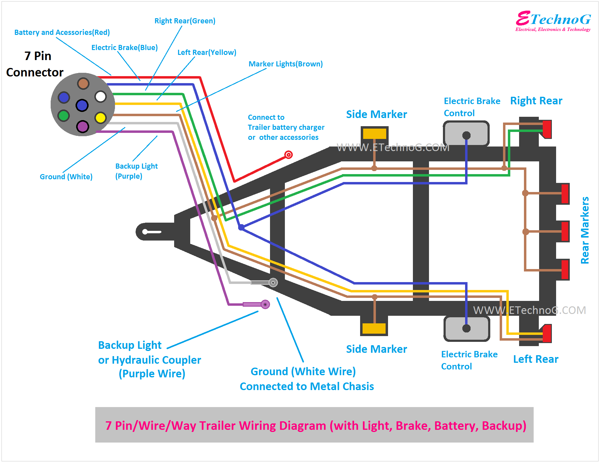
Alright, let's dive into the world of 7-blade trailer connectors. Whether you're fixing a malfunctioning trailer light, adding an electric brake controller, or just trying to understand how your tow vehicle communicates with your trailer, understanding the 7-blade wiring diagram is crucial. Think of it as the Rosetta Stone for trailer wiring – once you crack the code, you'll be able to diagnose and repair issues with confidence.
Why This Diagram Matters
The 7-blade connector, also known as the RV blade connector, is the most common type found on modern trailers and tow vehicles, especially those designed for heavier loads. It's not just about lights; it handles a variety of crucial functions. This diagram empowers you to:
- Troubleshoot lighting problems (brake lights, turn signals, running lights).
- Install or replace components like electric brake controllers, auxiliary power supplies, and reverse lights.
- Ensure safe and legal towing by verifying proper wiring and function.
- Customize your trailer wiring to suit specific needs.
- Understand the basic functionality of your towing system.
Let's face it: paying a shop for simple wiring fixes adds up quickly. Knowing this diagram allows you to tackle these projects yourself, saving you time and money.
Key Specs and Main Parts
Before we get into the diagram itself, let's define the key specs and components involved:
- Voltage: Primarily 12V DC (Direct Current). This is the standard automotive voltage.
- Current Rating: Varies depending on the circuit and wire gauge. Electric brakes draw significantly more current than lights, so the wiring is typically heavier. Always consult your trailer and tow vehicle manuals for specific current ratings.
- Wire Gauge: Heavier gauge wires (e.g., 12 AWG or 10 AWG) are used for high-current circuits like electric brakes and auxiliary power. Lighter gauge wires (e.g., 16 AWG or 18 AWG) are sufficient for lighting. Using the correct gauge is critical for safety and preventing voltage drop.
- The Connector: The 7-blade connector itself has distinct blades, each dedicated to a specific function.
The 7 blades are typically assigned as follows, although slight variations can occur (always double-check with your specific connector!):
- Ground (White): Provides the return path for all electrical circuits. A good ground connection is absolutely essential for proper operation.
- Tail/Running Lights (Brown): Powers the trailer's running lights.
- Left Turn/Stop (Yellow): Powers the left turn signal and brake light.
- Right Turn/Stop (Green): Powers the right turn signal and brake light.
- Electric Brakes (Blue): Connects to the electric brake controller in your tow vehicle. The intensity of the braking signal is proportional to the force applied by the brake controller.
- Auxiliary Power (Black): Provides 12V power from the tow vehicle to the trailer, often used for charging trailer batteries or powering interior lights. This circuit is often fused at a higher amperage.
- Reverse Lights (Purple): Powers the trailer's reverse lights.
Symbols – Decoding the Diagram
A wiring diagram isn't just a random assortment of lines and colors. It's a symbolic representation of the electrical circuit. Here's a breakdown of common symbols:
- Lines: Represent wires. The thickness of the line can sometimes indicate the wire gauge (thicker line = heavier gauge).
- Colors: Standardized wire colors are used to identify the function of each wire. The colors listed above (White, Brown, Yellow, Green, Blue, Black, Purple) are the most common.
- Connector Symbols: Show the physical connector with numbered or labeled blades.
- Ground Symbol: Usually a series of descending horizontal lines connected to a vertical line. Indicates connection to the vehicle chassis.
- Fuse Symbol: A zig-zag line enclosed in a rectangular box. Protects the circuit from overcurrent.
- Splice Symbol: A dot where two or more wires connect.
Understanding these symbols allows you to trace the path of electricity from the tow vehicle to the trailer and back, pinpointing potential problem areas.
How It Works
The 7-blade connector acts as a central hub for all electrical communication between the tow vehicle and the trailer. When you connect the trailer, each blade makes contact with its corresponding counterpart in the tow vehicle's receptacle. Here's a simplified explanation of how the key circuits function:
- Lighting: When you turn on your headlights, the tow vehicle sends power through the brown wire to the trailer's running lights. When you activate the turn signals or brakes, the yellow and green wires are energized, lighting the corresponding lights on the trailer.
- Electric Brakes: When the brake controller in the tow vehicle is activated, it sends a variable voltage signal through the blue wire to the trailer's electric brake magnets. The higher the voltage, the stronger the braking force.
- Auxiliary Power: The black wire provides a constant 12V power supply from the tow vehicle's battery to the trailer. This is often used to charge the trailer's battery, operate interior lights, or power other accessories. This circuit should always be fused near the tow vehicle's battery.
The white wire provides a critical ground connection. If this connection is poor or corroded, it can cause all sorts of electrical problems, from dim lights to malfunctioning brakes.
Real-World Use – Basic Troubleshooting Tips
Here are a few common troubleshooting scenarios and how the wiring diagram can help you:
- No Tail Lights: Check the brown wire connection at both the tow vehicle and trailer. Use a multimeter to test for voltage at the connector when the headlights are on. Also, inspect the tow vehicle's tail light fuse.
- One Turn Signal Not Working: Check the yellow (left) or green (right) wire connection. Inspect the bulbs on the trailer. Use a test light or multimeter to check for power at the connector when the turn signal is activated.
- Electric Brakes Not Working: Check the blue wire connection. Verify the brake controller in the tow vehicle is functioning correctly. Use a multimeter to check for voltage at the blue wire connector when the brake controller is manually activated. Inspect the wiring to the brake magnets on the trailer axles.
- Dim or Flickering Lights: This is often a sign of a poor ground connection. Clean and tighten the ground connections on both the tow vehicle and trailer.
Always use a test light or multimeter to diagnose electrical problems safely.
Safety – Highlighting Risky Components
Working with electrical systems can be dangerous. Here are some key safety precautions:
- Disconnect the Battery: Whenever possible, disconnect the negative battery terminal on both the tow vehicle and trailer before working on the wiring.
- Use a Multimeter: A multimeter is your best friend for diagnosing electrical problems. It allows you to safely measure voltage, current, and resistance.
- Proper Wire Connections: Use proper crimp connectors and heat shrink tubing to create secure and weather-resistant connections. Avoid using wire nuts in automotive applications.
- Fuses: Always use fuses of the correct amperage rating to protect the circuits.
- Overcurrent Protection: Be especially careful when working with the auxiliary power (black) and electric brake (blue) circuits, as they can carry significant current. Improper wiring or overloading these circuits can lead to overheating, fires, and damage to your vehicle.
- Don't Cut Corners: If you are not comfortable working with electrical systems, consult a qualified mechanic.
Remember, dealing with electrical circuits requires caution. A mistake could lead to a short circuit, damage to your vehicle, or even personal injury.
To help you further, we have a downloadable 7-blade trailer connector wiring diagram available. This detailed diagram includes color-coded illustrations and troubleshooting tips, making it an invaluable resource for your DIY projects.