7 Blade Trailer Plug Wiring Diagram Hopkins
Alright, let's dive into the wonderful world of 7-blade trailer wiring. If you're tackling trailer wiring repairs, upgrades, or even just trying to understand how your trailer lights are powered, understanding the 7-blade trailer plug wiring diagram is absolutely crucial. This isn't just about making sure your taillights work; it's about ensuring safe towing, proper brake function, and potentially even powering accessories within your trailer.
Purpose
The 7-blade trailer connector is the most common type for medium to heavy-duty trailers, particularly those with electric brakes. Knowing the wiring diagram allows you to:
- Diagnose and repair faulty trailer lighting or brake issues. No more guessing which wire goes where!
- Customize your trailer wiring for additional features, like reverse lights or auxiliary power.
- Ensure compatibility when switching between different tow vehicles and trailers.
- Comply with legal requirements regarding trailer lighting and braking. A faulty trailer can lead to hefty fines or worse.
Key Specs and Main Parts
Before we dissect the diagram, let's define the key components:
- 7-Blade Connector (Trailer Side): This is the male connector mounted on your trailer.
- 7-Blade Connector (Vehicle Side): This is the female connector mounted on your tow vehicle.
- Wiring Harness: The bundle of wires connecting the connectors to the trailer's lights, brakes, and other systems.
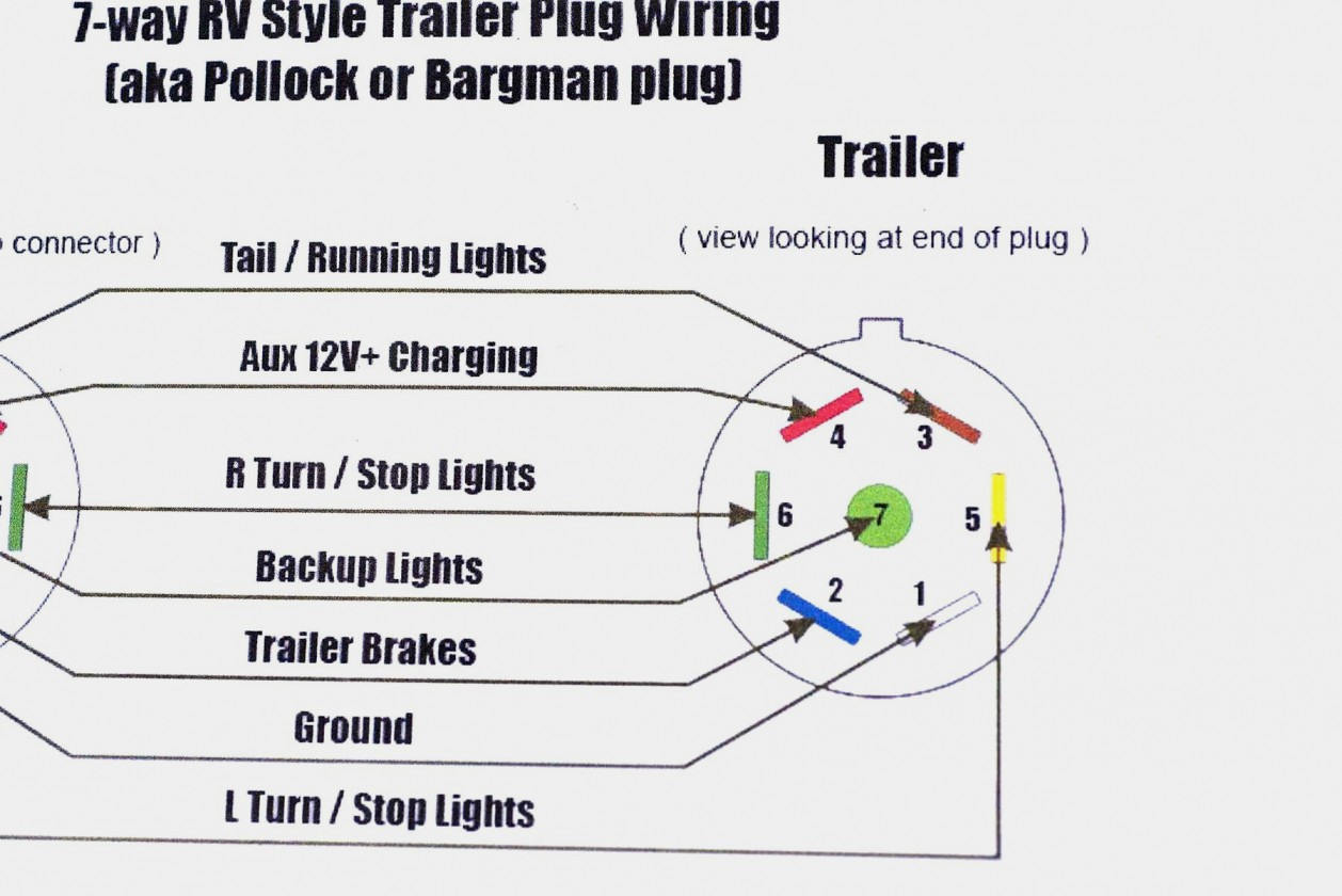
Each blade in the connector corresponds to a specific function. The standard wiring configuration for a Hopkins 7-blade connector is as follows:
- White: Ground (Return path for all circuits)
- Blue: Electric Brakes (Powers the trailer's electric brake magnets)
- Yellow: Left Turn/Brake Light (Combined function)
- Green: Right Turn/Brake Light (Combined function)
- Brown: Tail Lights/Running Lights (Illuminates the trailer's taillights and marker lights)
- Red: Auxiliary Power/Battery Charge (Provides a 12V DC power source to the trailer; often used to charge a trailer battery or power interior lights)
- Black: 12V Power (Direct connection to the tow vehicle's battery; typically used to power high-draw accessories). Important: This circuit should be fused at the tow vehicle.
Important Note: While this is the standard, always double-check the specific wiring diagram provided by Hopkins or the trailer manufacturer. Wiring can sometimes vary, especially on older or custom-built trailers.
Symbols - Decoding the Diagram
Understanding the symbols on a wiring diagram is crucial. Let's break down the most common ones:
- Solid Lines: Represent the actual wires connecting the components. The thickness of the line doesn't usually indicate wire gauge, but it might in some specialized diagrams.
- Dashed Lines: Sometimes indicate a wire that's present in some configurations but not others, or a shielded wire.
- Color Codes: Are essential. They show the color of the wire, making identification a breeze. For example, a solid blue line indicates a blue wire.
- GND Symbol (usually three horizontal lines descending in size): Indicates a ground connection. This should be connected to the trailer frame.
- Battery Symbol: Represents the 12V DC power source, usually the tow vehicle's battery.
- Light Bulb Symbol: Represents the trailer lights (taillights, brake lights, turn signals).
- Brake Magnet Symbol (usually a coil with an arm): Represents the electric brake magnets in the trailer's axles.
- Fuse Symbol: Indicates a fuse is installed in the circuit for protection.
- Connector Symbol: Shows where the wires connect to the 7-blade connector. Usually depicted as a series of rectangles representing the blades.
How It Works
The system is fairly straightforward. When you activate a function in your tow vehicle (e.g., turn signal, brake pedal), the corresponding signal is sent through the wiring harness to the trailer. Let's trace a few signals:
- Turn Signals: When you signal a left turn, the tow vehicle sends a 12V signal through the yellow wire to the trailer's left turn signal. The electricity flows through the light bulb, causing it to illuminate, and then back to the tow vehicle through the white (ground) wire.
- Brakes: When you press the brake pedal, the tow vehicle sends a 12V signal through the blue wire to the trailer's electric brake magnets. The magnets activate, pulling on the brake shoes and slowing the trailer. The circuit is completed through the white (ground) wire. The amount of voltage sent to the brakes depends on the brake controller settings in your vehicle, so the braking force is proportional.
- Taillights: When you turn on your headlights, the tow vehicle sends a 12V signal through the brown wire to the trailer's taillights and marker lights. These lights remain illuminated as long as the headlights are on.
- Auxiliary Power: The red wire is connected to a 12V source in the tow vehicle, often through a relay activated by the ignition. It provides a constant power supply to the trailer, which can be used to charge a trailer battery, power interior lights, or operate other accessories.
Real-World Use - Basic Troubleshooting Tips
Here's where the rubber meets the road. Let's say your trailer lights aren't working correctly:
- Check the Bulbs: Start with the simplest solution. A blown bulb is the most common culprit.
- Check the Connectors: Inspect both the vehicle-side and trailer-side connectors for corrosion, dirt, or damaged pins. Clean them with electrical contact cleaner.
- Test the Ground: A bad ground is a frequent cause of lighting problems. Ensure the white wire is securely connected to the trailer frame and the tow vehicle's chassis. Use a multimeter to check for continuity between the trailer frame and the tow vehicle's chassis.
- Use a Test Light or Multimeter: Use a test light or multimeter to check for voltage at each pin in the connector when the corresponding function is activated in the tow vehicle. If you're not getting voltage where you expect it, there's a problem with the tow vehicle's wiring or the trailer wiring harness.
- Isolate the Problem: If only one function is malfunctioning (e.g., only the left turn signal), focus on the wiring related to that specific function. If all the lights are out, the problem is likely a bad ground or a problem with the main power feed.
- Inspect the Wiring Harness: Look for frayed wires, loose connections, or damaged insulation along the entire length of the trailer wiring harness.
Example: Your trailer lights are dim. This could indicate a poor ground connection, corroded connectors, or undersized wiring.
Safety - Risky Components
Working with electrical systems always involves some risk. Pay particular attention to these areas:
- Battery Connection: When working with the auxiliary power (red) and 12V power (black) wires, disconnect the tow vehicle's battery to prevent short circuits and potential damage to the vehicle's electrical system.
- Brake Controller Wiring: The electric brake circuit carries significant current. Ensure the wiring is properly sized and protected with a fuse or circuit breaker. Never bypass the brake controller's protection.
- Damaged Wiring: Never work with frayed or damaged wires without properly insulating them. Exposed wires can create short circuits and pose a fire hazard.
- Working Under the Vehicle: Always use jack stands when working under a vehicle. Never rely solely on a jack.
Warning: Improper wiring can damage your tow vehicle's electrical system, the trailer's electrical system, or even cause a fire. If you're not comfortable working with electrical wiring, consult a qualified electrician or trailer repair technician.
By now, you should have a solid understanding of the Hopkins 7-blade trailer plug wiring diagram and how to troubleshoot common issues. Remember to always double-check the wiring diagram specific to your trailer and tow vehicle. And most importantly, work safely!
We have the detailed Hopkins 7-blade trailer plug wiring diagram file available for download. This resource provides a visual aid and detailed specifications that can be invaluable for your project.