7 Pin Electric Trailer Brake Wiring With Breakaway
Understanding and implementing a 7-pin electric trailer brake wiring system with a breakaway switch is crucial for safe and legal towing. This article will provide a comprehensive guide to the wiring diagram, its functionality, and essential troubleshooting tips, aimed at experienced DIYers and intermediate car owners.
Purpose of the 7-Pin Trailer Brake Wiring Diagram
This diagram serves as a roadmap for connecting your trailer's electrical system to your tow vehicle. It’s essential for several reasons:
- Repairs: Identifying and fixing faulty wiring issues.
- Upgrades: Adding or modifying trailer brake controllers or lighting systems.
- New Installations: Wiring a trailer from scratch or converting from a different connector type.
- Troubleshooting: Diagnosing electrical problems such as brake malfunctions, light failures, or battery charging issues.
- Legal Compliance: Ensuring your trailer meets safety regulations, especially regarding brakes and lighting.
- Learning: Gaining a deeper understanding of trailer electrical systems.
Without a clear understanding of the wiring diagram, you risk damaging your vehicle, trailer, or, more importantly, creating a dangerous situation on the road. Proper wiring ensures that your trailer lights function correctly (brake lights, turn signals, running lights), the electric brakes activate proportionally to your vehicle's braking, and the breakaway system is ready to prevent runaway trailers in the event of a disconnect.
Key Specs and Main Parts
The 7-pin connector is the standard for trailers with electric brakes. Here's a breakdown of the key components and their functions:
- 7-Pin Connector (Trailer End): This plug connects to the tow vehicle's 7-pin socket. It provides connections for all essential electrical functions.
- 7-Pin Socket (Vehicle End): Mounted on the tow vehicle, this socket receives the trailer's 7-pin connector.
- Electric Brakes: Electromagnets inside the trailer's brake drums that activate when current is applied. The amount of current determines the braking force.
- Brake Controller: A device installed in the tow vehicle that senses braking and sends a proportional current to the trailer's electric brakes. It uses an inertia sensor or connects to the vehicle's hydraulic brake system to determine braking force.
- Breakaway Switch: A crucial safety device. It's a switch connected to the trailer's brakes and a dedicated 12V battery on the trailer. A cable runs from the switch to the tow vehicle. If the trailer disconnects, the cable pulls the pin from the switch, activating the trailer brakes to prevent a runaway situation.
- Breakaway Battery: A small, dedicated 12V battery on the trailer, providing power to the brakes via the breakaway switch in an emergency. It is usually charged by the tow vehicle when connected.
- Wiring Harness: A collection of wires that connect all the components, typically using color-coded wires for easy identification.
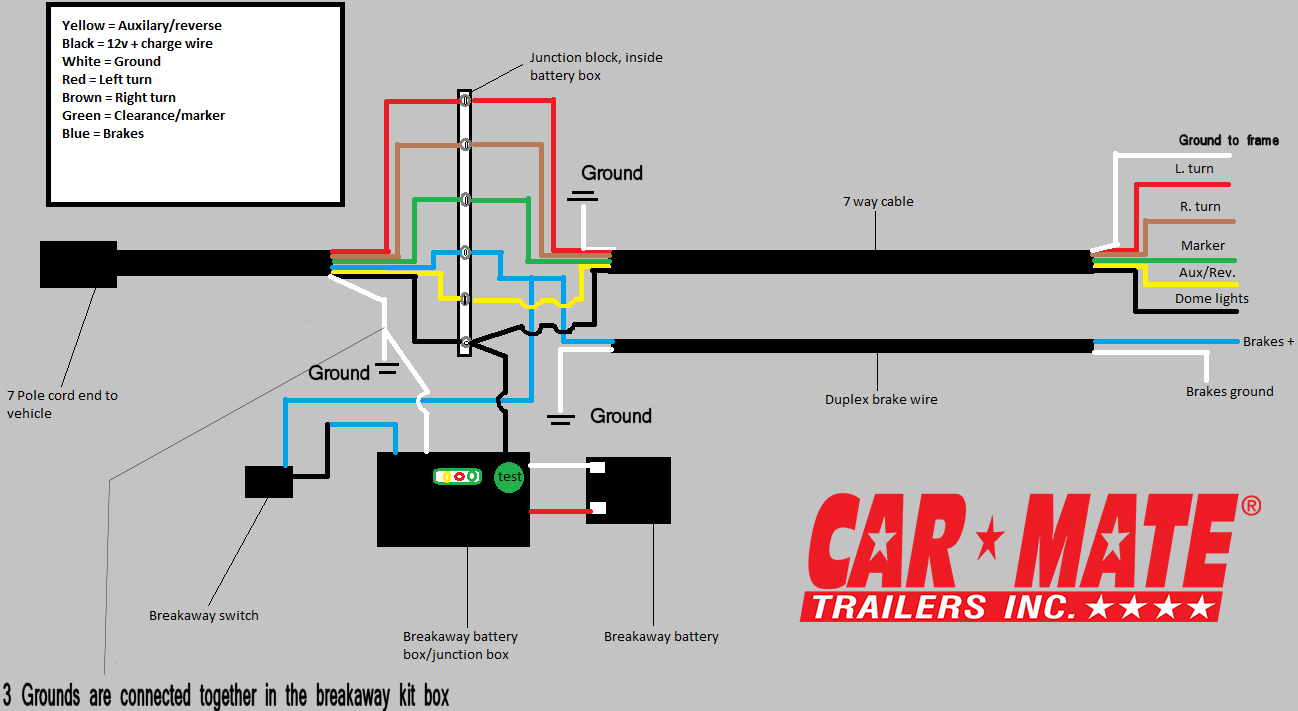
Symbols: Lines, Colors, and Icons
Understanding the symbols in the wiring diagram is crucial. Here's a common interpretation:
- Solid Lines: Represent wires. Their thickness might indicate the wire gauge (thicker lines usually mean thicker wires, which can handle more current).
- Dashed Lines: Might indicate grounding connections or connections that are made within a device, rather than an external wire run.
- Color Codes: Standard color codes are used for specific functions:
- White: Ground. The most critical connection for all circuits.
- Blue: Electric Brake Controller Output (to trailer brakes).
- Brown: Tail/Running Lights.
- Yellow: Left Turn/Brake Light.
- Green: Right Turn/Brake Light.
- Red: Breakaway Switch (from breakaway battery). Some configurations may use red for auxiliary power.
- Black: 12V+ Auxiliary Power (for charging the breakaway battery or other trailer functions).
- Icons: Schematic symbols for components like the brake controller, battery, breakaway switch, and lights are used. These are standard electrical symbols.
How It Works
The 7-pin system is designed to provide a standardized and reliable connection for several functions. Here's a simplified explanation of how the key components work together:
- Brake Controller Activation: When you apply the brakes in your tow vehicle, the brake controller senses the deceleration.
- Signal to Trailer Brakes: The brake controller sends a signal (variable voltage) through the blue wire to the trailer's electric brakes. The higher the voltage, the stronger the braking force.
- Electric Brake Engagement: The electricity energizes electromagnets inside the trailer's brake drums. These electromagnets pull on a lever, which applies the brakes.
- Lighting Operation: The brown, yellow, and green wires control the trailer's lights, mirroring the functions of the tow vehicle's lights (tail lights, turn signals, brake lights).
- Breakaway System Activation: If the trailer becomes disconnected from the tow vehicle, the breakaway cable pulls the pin from the breakaway switch. This completes a circuit between the breakaway battery and the trailer's brakes, activating the brakes to bring the trailer to a stop. This is a critical safety feature!
- Auxiliary Power: The black wire provides 12V+ power from the tow vehicle to the trailer. This power is commonly used to charge the breakaway battery or power other trailer accessories. It is important to fuse this circuit appropriately.
- Grounding: The white wire provides a common ground for all circuits. A good ground connection is essential for proper operation of all electrical components.
Real-World Use: Basic Troubleshooting Tips
Here are some common problems and troubleshooting steps:
- No Trailer Brakes:
- Check the brake controller settings.
- Inspect the blue wire connection.
- Test the trailer brake magnets with a multimeter (resistance check). An open circuit means the magnet is bad.
- Verify the ground connection (white wire).
- Lights Not Working:
- Check the tow vehicle's fuses.
- Inspect the corresponding wire connections (brown, yellow, green).
- Check the bulbs and sockets.
- Verify the ground connection (white wire).
- Breakaway System Not Working:
- Test the breakaway battery with a multimeter.
- Check the breakaway switch connection.
- Inspect the wiring between the battery, switch, and brakes.
- Erratic Brake Operation:
- Check for corrosion on the brake controller wiring.
- Adjust the brake controller settings.
- Inspect the trailer brake magnets for wear or damage.
Safety: Highlight Risky Components
Working with electrical systems always carries risks. Here are some specific safety considerations:
- Battery Disconnect: Always disconnect the tow vehicle's battery before working on the electrical system to prevent short circuits.
- Fuse Protection: Use appropriately sized fuses for all circuits to protect against overloads and short circuits. Never bypass a fuse.
- Wire Gauge: Use the correct wire gauge for the amperage requirements of each circuit. Undersized wires can overheat and cause fires.
- Waterproofing: Protect all connections from moisture to prevent corrosion and short circuits. Use dielectric grease on connectors.
- Brake Controller Installation: Follow the brake controller manufacturer's instructions carefully. Incorrect installation can lead to brake malfunctions.
- Breakaway Battery Maintenance: Regularly check the breakaway battery's charge level and replace it as needed. A dead battery renders the breakaway system useless.
- Proper Grounding: Ensure all ground connections are clean, tight, and corrosion-free. A poor ground can cause a variety of electrical problems.
Working with trailer wiring requires care and attention to detail. Always double-check your work and consult the wiring diagram to ensure correct connections. If you are unsure about any aspect of the wiring, consult a qualified professional.
We have a downloadable, high-resolution wiring diagram available. Contact us to obtain the file.