7 Pin Ford F250 Wiring Diagram For Trailer Lights
If you're an experienced DIYer, you understand the importance of having a reliable wiring setup for your trailer lights, especially when hauling with a Ford F250. This article serves as your comprehensive guide to understanding the 7-Pin Ford F250 wiring diagram for trailer lights. Whether you're performing repairs, upgrading your existing setup, or simply trying to understand how everything works, this breakdown will provide the knowledge you need.
Purpose of Understanding the 7-Pin Wiring Diagram
Knowing your 7-Pin trailer wiring inside and out is crucial for several reasons:
- Repairing Faults: Quickly identify and fix wiring issues that cause malfunctioning lights. This saves you time and money on professional repairs.
- Upgrading Your System: Understanding the wiring allows you to confidently add features like a trailer brake controller or auxiliary power.
- Ensuring Safety: Properly functioning trailer lights are essential for safety on the road, protecting you and other drivers. Faulty wiring can lead to accidents.
- Learning and Expanding Your Knowledge: As an experienced DIYer, comprehending electrical systems expands your skillset and gives you more confidence to tackle complex automotive projects.
Key Specs and Main Parts
The 7-Pin connector, also known as a 7-way connector, is the industry standard for heavy-duty towing. It provides connections for all essential trailer lighting and often includes additional circuits for brakes and auxiliary power. Here are the key components we'll be dealing with in the diagram:
- 7-Pin Connector (Vehicle Side): Mounted on your Ford F250, this receptacle provides the connection point for the trailer's wiring harness.
- 7-Pin Connector (Trailer Side): Plugs into the vehicle-side connector, completing the electrical circuit.
- Wiring Harness: A bundle of wires connecting the trailer lights to the 7-Pin connector.
- Individual Wires: Each wire within the harness carries a specific signal to the trailer.
- Fuses: Protect the circuits from overloads. Knowing which fuse controls each function is critical for troubleshooting.
- Relays (Optional): Some F250 models might use relays to switch power to specific trailer functions.
Symbols in the Wiring Diagram: Deciphering the Language
Wiring diagrams use a standardized set of symbols to represent electrical components and connections. Understanding these symbols is key to reading the diagram correctly. Here's a breakdown of the most common ones you'll encounter:
- Lines: Represent wires. A solid line indicates a direct electrical connection. Dashed lines might indicate a shielded wire or a wire that only exists in certain configurations. The thickness of the line *does not* usually represent wire gauge.
- Circles with Numbers: Represent the individual pins within the 7-Pin connector. Each pin number corresponds to a specific function (e.g., pin 1 for ground, pin 4 for right turn/brake).
- Colors: Each wire is color-coded to help identify its function. Common colors include White (Ground), Brown (Tail Lights), Yellow (Left Turn/Brake), Green (Right Turn/Brake), Red (Stop Lights), Blue (Electric Brakes), and Black (Auxiliary Power). *Always verify the color coding on your specific vehicle and trailer*, as variations can occur.
- Ground Symbol (⏚): Indicates a connection to the vehicle's chassis ground, which provides a return path for the electrical current.
- Fuse Symbol (⏷): Represents a fuse, the sacrificial component that protects the circuit from overcurrent. The diagram will usually indicate the fuse's amperage rating.
- Relay Symbol (⧖): Represents a relay, an electrically operated switch that allows a low-current circuit to control a high-current circuit.
- Light Bulb Symbol: Represents a light bulb (taillight, brake light, turn signal, etc.).
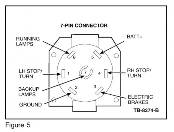
How It Works: Functionality of Each Pin
The 7-Pin connector provides a standardized set of connections for essential trailer lighting and braking functions. Here's a breakdown of each pin and its corresponding function. Remember that wire colors are typical, but always verify with a multimeter:
- Pin 1: White Wire - Ground Return: This is the most crucial connection. It provides the return path for all electrical current flowing to the trailer lights and brakes. A poor ground connection is the most common cause of trailer lighting problems.
- Pin 2: Blue Wire - Electric Brakes: This pin carries the signal from the trailer brake controller in your F250 to the electric brakes on the trailer. The voltage on this pin is proportional to the braking force applied by the driver.
- Pin 3: Green Wire - Right Turn Signal and Brake Light: This wire carries the signal for both the right turn signal and the right brake light on the trailer.
- Pin 4: Black Wire - 12V Auxiliary Power: This pin provides a constant 12V power source to the trailer. It can be used to charge a trailer battery, power interior lights, or run other auxiliary devices. This circuit is often fused and may be switched via a relay.
- Pin 5: Brown Wire - Taillights and Side Marker Lights: This wire carries the signal to the taillights and side marker lights on the trailer. It is activated when the headlights of your F250 are turned on.
- Pin 6: Red Wire - Stop Lamps: This wire carries the dedicated stop lamp signal to the trailer.
- Pin 7: Yellow Wire - Left Turn Signal and Brake Light: This wire carries the signal for both the left turn signal and the left brake light on the trailer.
Real-World Use: Basic Troubleshooting Tips
Here are some common trailer wiring problems and how to troubleshoot them using the 7-Pin wiring diagram:
- No Lights at All: Check the ground connection first. A poor ground is the most common culprit. Use a multimeter to verify continuity between the trailer frame and the vehicle's chassis ground. Also, check the main fuses in your F250 that supply power to the trailer connector.
- One Light Not Working: Use the wiring diagram to identify the wire that controls the malfunctioning light. Check the connection at the 7-Pin connector on both the vehicle and the trailer. Use a test light or multimeter to verify that the correct voltage is present at the connector when the corresponding signal is activated (e.g., turn signal, brake light). Check the bulb itself.
- All Lights Dim: This is often caused by a voltage drop due to corroded connections or undersized wiring. Inspect all connections for corrosion and clean them thoroughly. Consider upgrading to heavier gauge wiring if necessary.
- Brakes Not Working: Verify that your trailer brake controller is properly installed and calibrated. Use a multimeter to check for voltage on the blue wire (Pin 2) when the brake pedal is pressed. Inspect the brake magnets on the trailer for damage.
Using a Multimeter: A multimeter is your best friend when troubleshooting electrical problems. Learn how to use it to check for voltage, continuity, and resistance. Always disconnect the power source before probing live wires to avoid electric shock.
Safety Precautions
Working with electrical systems can be dangerous if proper precautions are not taken. Here are some important safety tips:
- Disconnect the Battery: Before working on any electrical wiring, disconnect the negative terminal of your F250's battery to prevent accidental shorts and electric shock.
- Wear Safety Glasses: Protect your eyes from sparks and debris.
- Use Insulated Tools: Use tools with insulated handles to prevent electric shock.
- Work in a Well-Ventilated Area: When soldering, work in a well-ventilated area to avoid inhaling harmful fumes.
- Identify the Hot Wires: Before cutting or splicing any wires, use a circuit tester to identify the hot (positive) and ground (negative) wires.
- Be Careful with the Auxiliary Power Wire (Black): This wire carries constant 12V power and can cause a short circuit if accidentally grounded. Always disconnect the power source before working with this wire.
The Trailer Brake Controller is a critical safety component. If you're unsure about wiring or calibrating it, seek professional assistance. Improper brake controller operation can lead to accidents.
Remember to always double-check your work and test the lights before hitting the road. A few minutes of preventative maintenance can save you a lot of headaches (and potential accidents) down the line.
For a more detailed visual aid, we have a downloadable 7-Pin Ford F250 wiring diagram available. You can access it for a clearer understanding of the connections and wire routing. Happy towing!